Measured parameters and mechanical mounting
The family measures vibration, temperature, current, rotational speed and any signal the asset already produces. All parameters are recorded in a single database on a common timeline and evaluated against the same alarm logic, which allows a current signature and a vibration step to be assessed as one event rather than as two unrelated records.
For vibration, each sensor transmits the complete time waveform and the full FFT spectrum rather than a scalar value. The PHANTOM® Gen 4 provides 8 kHz of usable bandwidth with 12,800 lines of resolution in triaxial measurement and 25,600 lines in single-axis measurement.
The sensors are stud-mounted and require no signal cabling or conduit. Mounting follows the practice described in ISO 5348 for the mechanical mounting of accelerometers. Measurement points can therefore be instrumented in minutes, including assets for which a wired installation was not economically justifiable.
Between scheduled recordings, the vibration sensors additionally transmit RMS velocity, integrated on board in order to limit transmission energy. An internal alarm threshold can be configured remotely to wake the sensor when vibration exceeds the configured limit.
11 sensors
One wireless family
65,000
Measurements per battery
100 m – 3 km
Range, line of sight
Wireless transmission of condition monitoring data
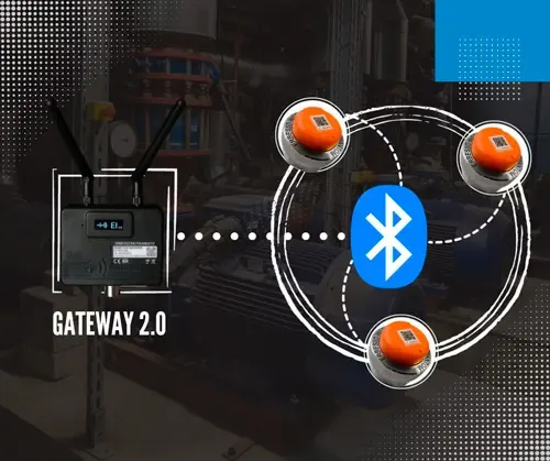
The complete time waveform and the FFT spectrum are transmitted over Bluetooth Low Energy 5.0. The sensor transmits the full measurement rather than a single scalar value, while power consumption remains low enough for several years of operation on one cell. The transmission range is up to 100 m with line of sight and approximately 50 m through intermediate walls, depending on wall construction and thickness.
The PHANTOM® Gen 4 provides 8 kHz of bandwidth and a configurable dynamic range: ±15, ±30 or ±60 g in the high-range version and ±4, ±8 or ±16 g in the high-sensitivity version. The same product family therefore covers both low-amplitude and high-amplitude applications. The reporting interval is configurable from one minute upwards and is the principal factor determining battery service life.
Alarm handling

Alarm thresholds and measurement triggering
The vibration sensors evaluate measurements on board and do not wait for the next scheduled transmission to detect an exceedance. An internal processor assesses the vibration signal against the configured limits within a fraction of a second. If the limits are exceeded, the sensor transmits an alarm immediately to the platform and, where configured, to a mobile device.
Alarm thresholds are configured per parameter, so that each sensor is evaluated against limits appropriate to the quantity it measures.
On-board evaluation allows the sensor to remain in standby for approximately 95 % of its operating time without the risk of an event occurring unrecorded between two scheduled readings. Transmission energy is expended only when a measurement or an alarm requires it.
After an alarm has been transmitted, the sensor does not repeat it unless a subsequent measurement exceeds the previous value by more than 25 %.
Cross-triggering between sensors
A threshold exceeded on one sensor can initiate a measurement on another. The gateway coordinates the sequence, which completes within seconds. When the speed sensor detects that the machine has reached a defined rotational speed, it initiates a vibration recording, so that the measurement is acquired at the relevant operating condition rather than at an arbitrary point in the reporting schedule.
The general purpose inputs provide the same function for any variable already instrumented on the asset — pressure, flow, level, temperature or any other signal connected to a 4–20 mA, 0–10 V or ±2 Vpp channel. Measurements initiated in this way are acquired at the same instant, which is a precondition for correlating two parameters on a common timeline.
Construction

Battery service life and replacement
The vibration sensors are powered by a CR2477 lithium coin cell rated for 65,000 measurements, corresponding to several years of service at typical reporting intervals. Actual service life depends on the configured reporting interval, the ambient operating temperature and the distance between the sensor and its gateway.
The modules for the remaining parameters use two replaceable AA lithium cells. They can alternatively be supplied from an external 5–24 V DC source where power is available at the measurement point; in that configuration no battery replacement is required.
All cells are user-replaceable. The service life of a sensor is therefore not limited by the service life of its cell: the cell is exchanged and the instrument remains in service.
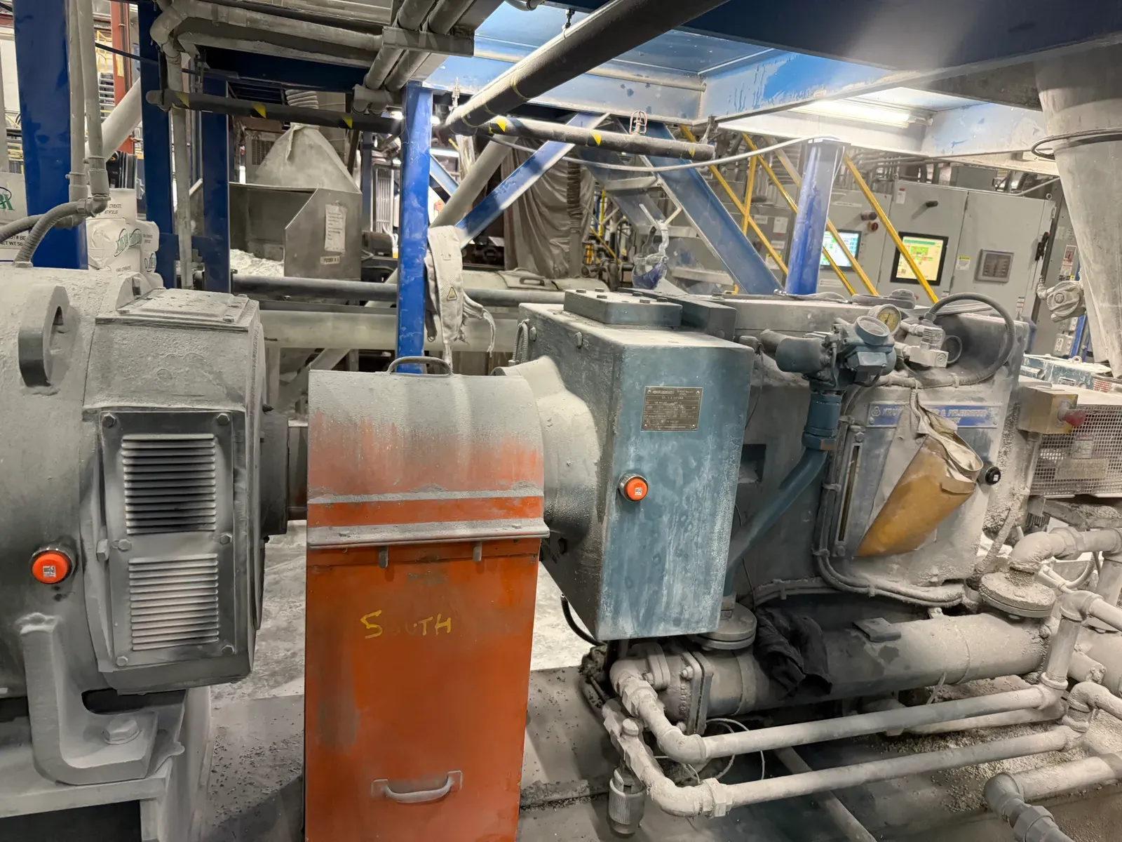
Permanent installation of condition monitoring sensors, indoors and outdoors
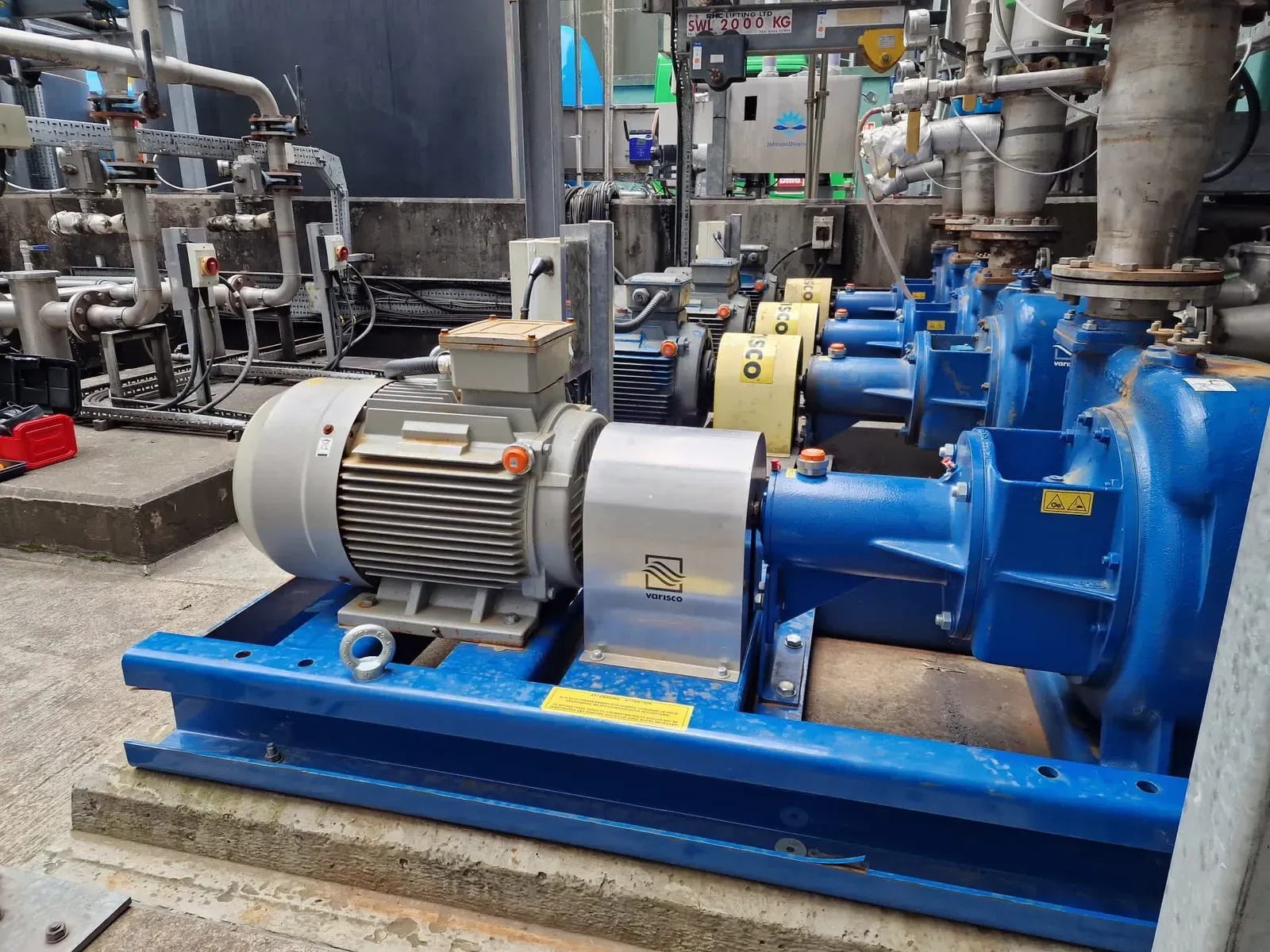
The sensors are designed for permanent installation, including outdoor locations. The enclosure is rated IP69 to IEC 60529 for protection against dust ingress and against high-pressure, high-temperature water jets. A repositionable base plate allows the sensor axes to be aligned with the machine axes, which is a precondition for comparable directional measurements.
The mounting method is selected according to the asset: the base plate is bonded with industrial epoxy adhesive, or the sensor is screwed directly onto a 1/4-28 UNF stud where one is already fitted.
Integrated temperature measurement and ambient operating range
Each sensor includes an integrated temperature element that serves two functions: it contributes to the machine temperature trend, and it issues an alarm when the configured limits are exceeded. It also issues an immediate warning if the measured temperature places the sensor itself at risk.
The ambient operating range of the sensor is −10 °C to 85 °C. Thermal insulators extend this range for assets operating above that limit.
Measured parameters and their diagnostic coverage
No single measured quantity detects every fault mode, which is why the family covers six. Each quantity is acquired by a dedicated sensor and recorded in the same database, so that a fault visible only in the current signature and a fault visible only in the vibration spectrum appear on a common timeline.
Product overview
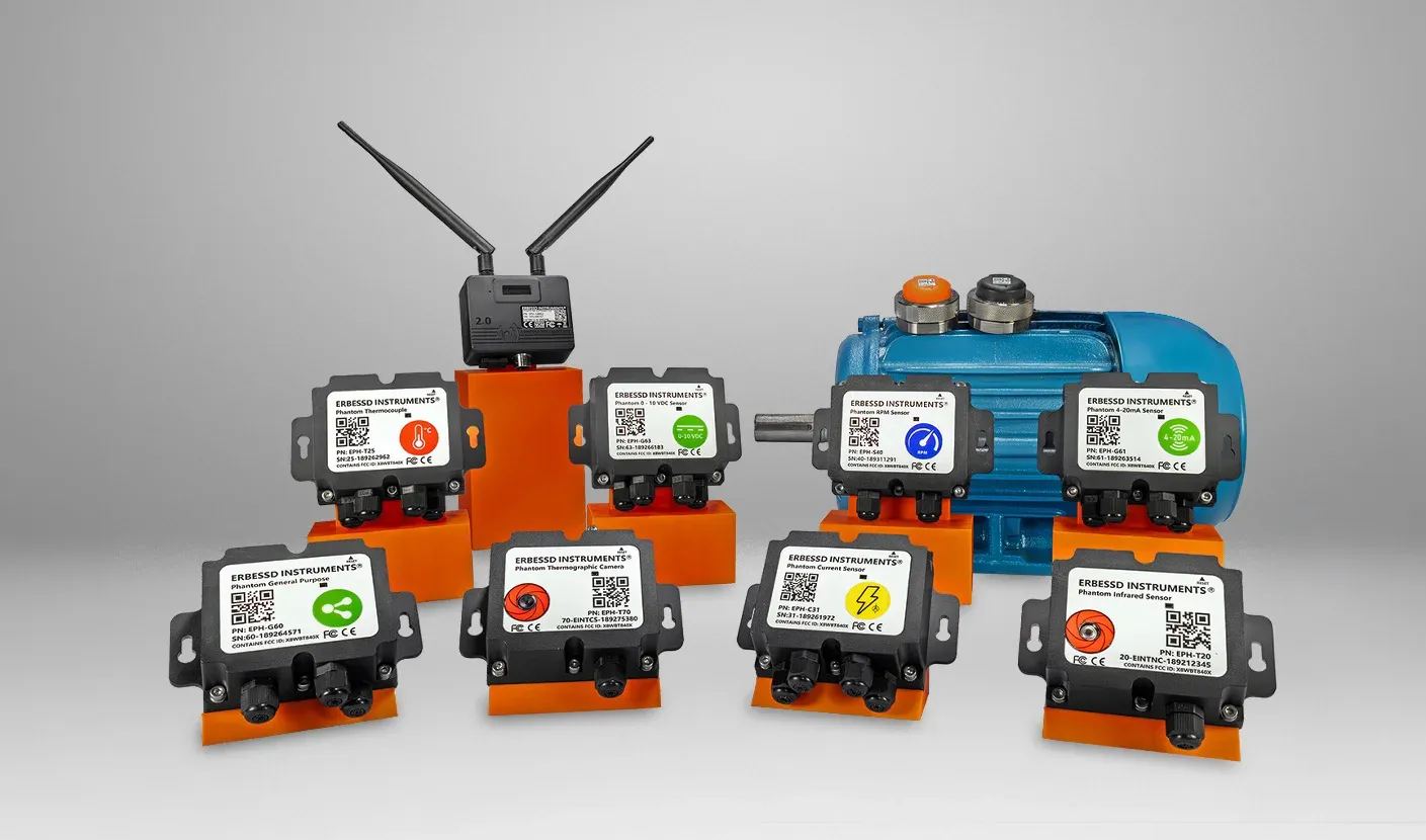
Product overview: the eleven PHANTOM® sensors
All sensors in the family use the same gateway, the same software and the same database. The values listed below correspond to those shown on the individual product cards, and each model links to its own product page.
| Sensor | What it measures | Code | Buy online |
|---|---|---|---|
| PHANTOM® Gen 4 Vibration Sensor | Triaxial vibration — waveform and spectrum, ATEX and IECEx | EPH-V83 · EPH-V82 | Buy |
| PHANTOM® Max | Triaxial vibration over distance — 3 km line of sight | EPH-V81 | Buy |
| Wireless Temperature Sensor | Contact temperature, any thermocouple, −270 °C to 1,372 °C | EPH-T25 | Buy |
| Wireless Temperature Sensor | Surface temperature without contact, −70 °C to +380 °C | EPH-T20 | Buy |
| Thermographic Camera | Thermal image of a surface within one metre | EPH-T70 | Buy |
| Wireless Current Sensor | 4 phases at once, clamps for 50, 100, 250 or 500 A | EPH-C31 | Buy |
| Wireless Speed Sensor | Rotation speed by Hall effect, up to 600,000 RPM | EPH-S40 | Buy |
| Wireless 2VDC Pk-Pk Sensor | Any 2 Vpp signal, 2 channels | EPH-G60 | Buy |
| Wireless 4-20mA Sensor | Any 4–20 mA signal, 4 channels | EPH-G61 | Buy |
| Wireless Dry Contact Sensor | Open or closed circuit, 4 channels | EPH-G62 | Buy |
| Wireless 0-10 VDC Sensor | Any 0–10 VDC signal, 4 channels | EPH-G63 | Buy |
The PHANTOM® family
PHANTOM® condition monitoring sensors: product range
The four general purpose models allow existing instrumentation to be retained. An existing signal is connected to the module and becomes an additional measurement point on the same wireless network.
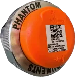
- 8 kHz Fmax high range · 4 kHz high sensitivity
- Full waveform and spectrum data
- Configurable sample rate: 32 kHz max
- Resolution lines: 12,800 triaxial · 25,600 single axis
- Dynamic range ±15/30/60 g or ±4/8/16 g
- ATEX and IECEx certified, gas and dust
- IP69 protection grade

- Range of -270 °C to 1,372 °C
- Measures temperature for object and ambient
- Connect any type of Thermocouple
- Configurable Alarm value
- Standby mode and long battery life
- IP67 Protection
- 2 Replaceable LiON AA batteries
- Optional 5–24 V DC external supply

- Measures temperature for object and ambient
- Measure Range from -70 to +380°C
- Configurable Alarm value
- Standby mode and long battery life
- Optional 5–24 V DC external supply
- Configure your sensor using your mobile
- IP67 Protection

- Thermal image of any surface within one metre
- Measures temperature for object and ambient
- Configurable Alarm value
- Standby mode and long battery life

- Measures 4-Phase current simultaneously
- Sends every 5min the max. value of a 15s reading
- Compatible AC Split-core Clamps (50A, 100A, 250A, 500A)
- Configurable Alarm value
- Standby mode and long battery life
- 2 Replaceable LiON AA batteries
- Optional 5–24 V DC external supply
- IP67 protection

- Switching Speed up to 600,000 RPM
- Speed + Vibration sensor integration
- Standby mode and long battery life
- Configurable Measurement Interval
- Configurable Alarm value
- 2 Replaceable LiON AA batteries
- Optional 5–24 V DC external supply
- IP67 protection

- Measures 2 Channels simultaneously
- Connect your accelerometer, proximeter or velocimeter
- Very Easy to install
- Configurable Alarm value
- Standby mode and long battery life
- Optional 5–24 V DC external supply
- IP67 protection

- Measures 4 Channels simultaneously
- Compatible with any 4-20mA sensor output
- Very Easy to install
- Configurable Alarm value
- Standby mode and long battery life
- Optional 5–24 V DC external supply
- IP67 protection
PHANTOM® Max: extended transmission range
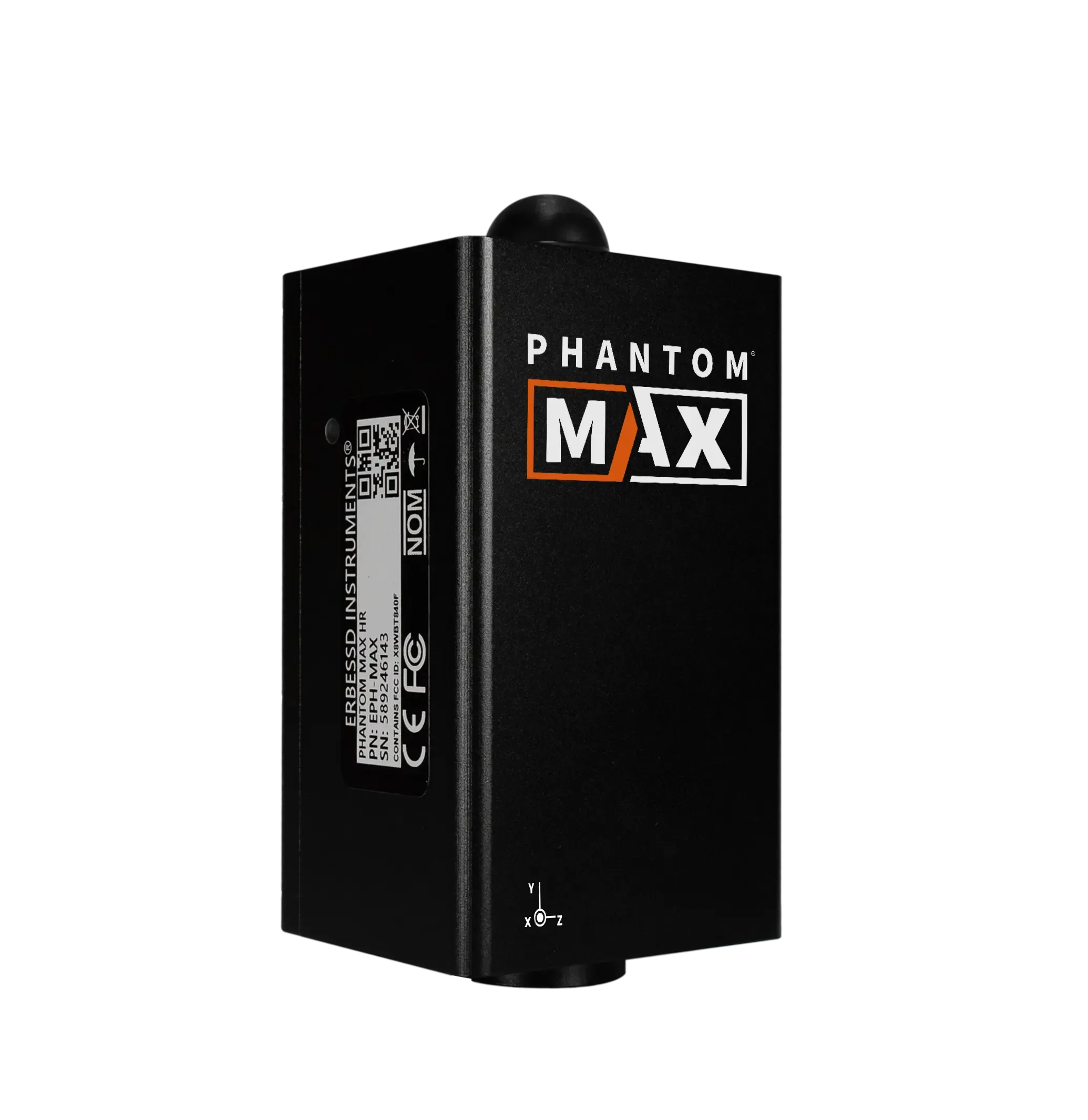
PHANTOM® Max is intended for assets located beyond the range of a standard gateway. The transmission range is 3 km with line of sight, verified in field testing, compared with 100 m for the remainder of the family. Remote pump houses, tank farms and towers can therefore be monitored without installing an additional gateway and network connection at the location.
The sensor samples at 32,000 Hz and resolves up to 204,800 lines in single-axis analysis, the highest resolution in the family. The anodised aluminium enclosure is rated IP69 to IEC 60529. Two models are available: EPH-V81 (high range) and EPH-V80 (high sensitivity).
PHANTOM® Max uses the same gateway, software and database as the remainder of the family. Extending the transmission range does not introduce a second system.
Gateway and data storage
Data storage and ownership
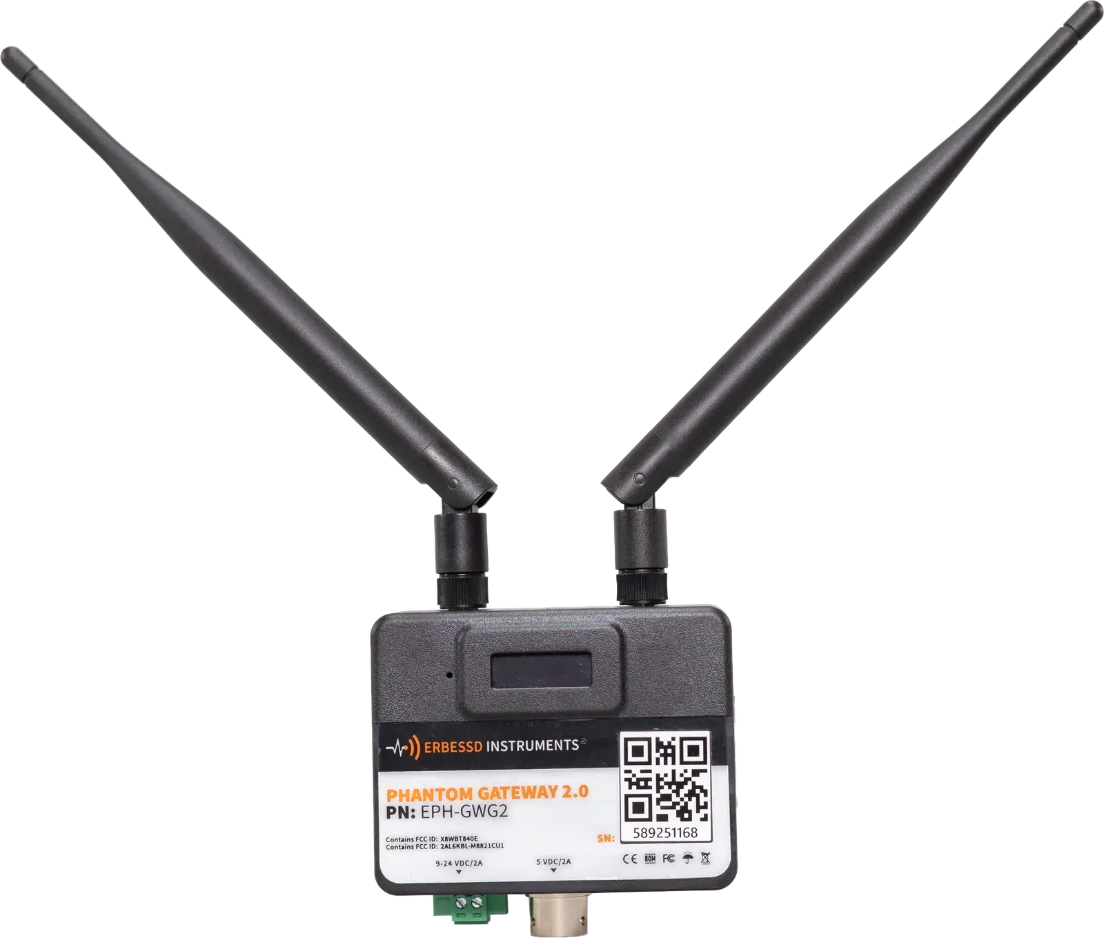
One PHANTOM® Gateway collects the measurements from all sensors within range and buffers them on board during network interruptions. The gateway does not determine where the data is subsequently stored. That decision remains with the operator and should be taken deliberately: the storage location is the element of a condition monitoring system that is most difficult to change once the programme is in operation.
Storage destinations
| Where the data lives | How it gets there | What you need |
|---|---|---|
| SQL database on a customer-owned server | Digivibe MX® writes the complete database to a Windows system within the plant; EI-Analytic™ can be installed on premises | No internet connection is required and no data leaves the site |
| EI-Analytic™, the Erbessd cloud | The gateway transmits over the plant network | An internet connection, either the plant network or a separate service |
| Plant historian, SCADA or MES | The gateway publishes over Modbus TCP/IP, OPC UA (IEC 62541) or MQTT (ISO/IEC 20922) | A client on the customer side |
| Customer-developed software | The published PHANTOM® API and drivers | Development resources and the drivers |
All four destinations use protocols already established in industrial plants, so no data is required to pass through Erbessd software.
Ownership of measurement data
The measurement data belongs to the operator, irrespective of where it is stored. Erbessd Instruments does not claim ownership of customer measurements, does not sell them and does not use access to them as a commercial instrument. Data held in EI-Analytic™ can be exported in full on request.
The storage destination can be changed at any time without loss of history. A programme may begin on a server within the plant and add the cloud when a second site is included, or begin in the cloud and be transferred to local infrastructure at a later date. The sensors and the gateway remain unchanged and the recorded history is retained. The storage destination is a configuration setting rather than a long-term commitment.
Software
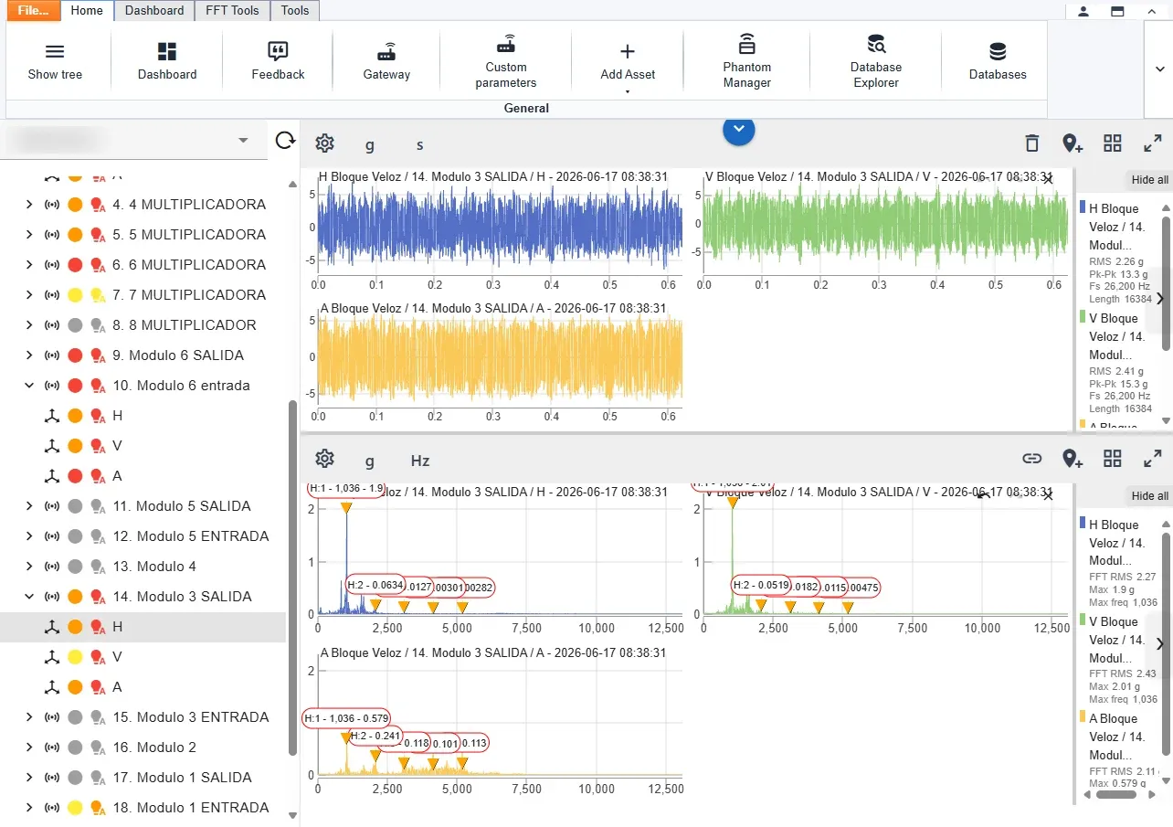
Digivibe MX®: analysis software for Windows
Digivibe MX® supports every PHANTOM® condition monitoring sensor and reads the data from either storage location — the Erbessd cloud or a local database held on the customer’s own system.
It provides the detailed analysis functions of the system: vibration analysis, trending, bearing diagnostics and 3D simulation. Sensor configuration is also carried out from this application.
Configurable dashboards at every hierarchy level
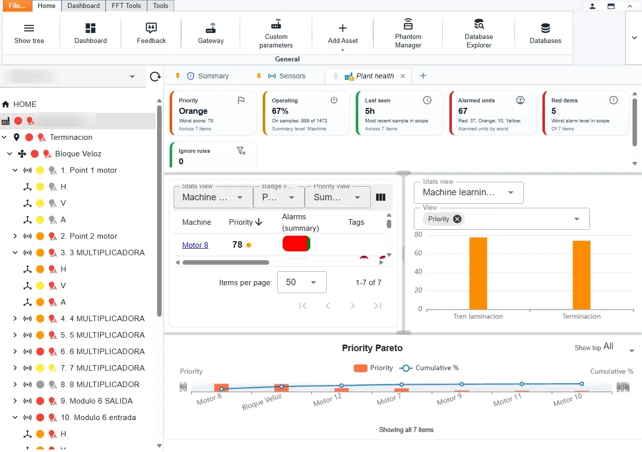
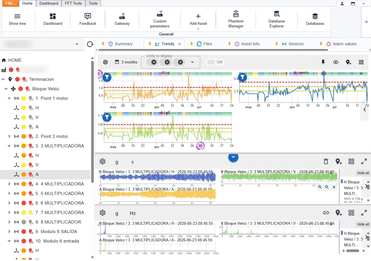
Dashboards are configured by the user and the number of dashboards is not limited. There is no fixed set of predefined views: a dashboard can cover the complete plant, an area, an individual machine or a single measurement point, and both the indicators displayed and their arrangement are selected by the user.
The two examples shown below are illustrative. The first ranks every machine in the plant by priority and identifies those currently in alarm. The second shows three months of trend data for one measurement point against its configured alarm thresholds.

WiSER VIBE®: mobile application
WiSER VIBE® provides access to the same measurement data on a mobile device, together with the principal analysis functions required in the field. The application is used to:
Receive alarm notifications on a mobile device when machine vibration exceeds the configured limit.
Analyse spectra on the mobile device. Time waveforms and spectra are available in all measurement parameters — velocity, displacement and acceleration envelope — which is sufficient for the assessment of bearings and gearboxes on site.
Review trends and statistics for each machine, on charts configured so that deviations are readily identifiable.


EI-Analytic™: web platform, cloud or on premises
EI-Analytic™ is operated either in the Erbessd cloud or on premises, on a server owned by the customer. The platform is identical in both cases. Plants whose data may not leave the site therefore retain the complete platform within their own network.
The platform holds the measurement history and performs the analysis. It stores every measurement, applies the machine learning that derives each alarm limit from the behaviour of the individual machine, and provides a remote analyst with the same spectra available locally.
No software installation is required. The platform is accessed through a web browser for review of trends, statistics and spectra, for configuration of any sensor and for monitoring the battery status of the installed base.
An integrated assistant, Erby, is available within the platform for the review of alarms, trends and spectra and for the preparation of maintenance cases and reports. It operates on the measurement history of the installation rather than on a generic model of machine behaviour, and submits any change for confirmation before it is applied. How a vibration assistant is trained.
Parameter-specific visualisation
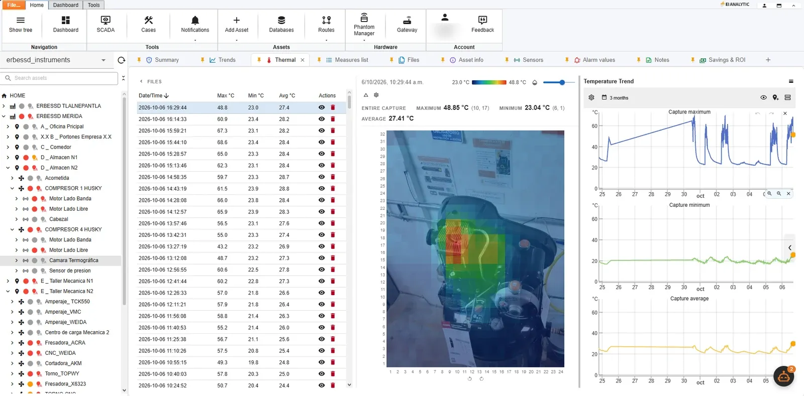
Each measured quantity is presented in the form appropriate to it, within the same platform. A vibration point is reviewed as a time waveform and a spectrum. A thermographic camera is reviewed as a thermal image with its measured maximum, minimum and average temperature, together with the trend of each of those three values over the selected period. The views are available for the same asset and on the same time axis.
This is the practical consequence of multi-parameter monitoring. A compressor instrumented with vibration points, a thermographic camera and a pressure input is assessed from three independent records of the same machine, acquired on one timeline. A fault that is not evident in one measured quantity is frequently evident in another.
Return on investment
Savings and return on investment
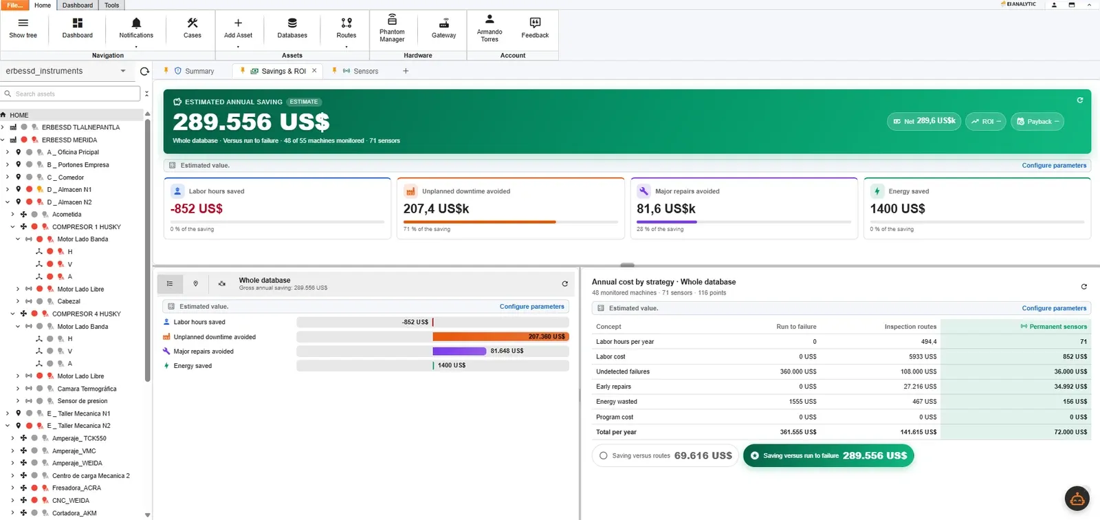
EI-Analytic™ calculates the estimated saving generated by the programme and presents it in four categories: labour hours, unplanned downtime avoided, major repairs avoided and energy. The three maintenance strategies — run to failure, scheduled inspection routes and permanent monitoring — are then costed side by side.
The figures are estimates derived from the asset register of the plant and from parameters configured by the customer. The example shown is the Erbessd Instruments plant: 48 machines and 71 sensors.
Ordering
Ordering options
Three ordering routes are available and the delivered hardware is identical in each. The sensors, gateway, software and database are the same; the routes differ in who specifies the installation, who holds title to the equipment and who provides subsequent support. A programme started on a rental basis can be converted to purchase without any change to the installed equipment.
Direct purchase
Purchase the sensors outright
Appropriate where the required sensors and quantities are already defined. All models shown on this page are listed in the online store with prices and stock; vibration sensors are also supplied in 4-sensor and 12-sensor kits. The hardware is purchased outright and the software is included.
Plant programme
Request a quotation for the programme
Appropriate for plant-wide programmes requiring specification before commitment. Erbessd Instruments reviews the asset register, specifies the sensors and the gateway coverage, and quotes the programme including installation and training.
Distributor
Purchase or rent through a distributor
Appropriate where local support in the customer’s language and time zone is required. The hardware is identical and the distributor provides its own analysis service. A number of distributors rent PHANTOM® sensors rather than selling them.
Frequently asked questions
How do I buy PHANTOM® sensors?
All sensors shown on this page are available directly from the Erbessd Instruments store, with prices and stock indicated. Vibration sensors are also supplied in 4-sensor and 12-sensor kits. For a plant-wide programme, or where the point count and gateway coverage require specification first, a quotation should be requested instead.
Can I rent the sensors instead of buying them?
Rental is available through the distributor network. Erbessd Instruments sells the hardware outright; a number of distributors rent PHANTOM® sensors, generally together with their own analysis service and on their own commercial terms. The same sensors can subsequently be purchased without any change to the installation. The distributor directory lists the options available by region.
Where does the data end up, and can I keep it on my own server?
The data can be held entirely on a customer-owned server; this is the first of the supported options. Digivibe MX® maintains the complete SQL database on a Windows system within the plant without an internet connection, and EI-Analytic™ can be installed on premises on a customer-owned server, providing the web platform without the data leaving the site. The Erbessd cloud may be added as an additional destination. The data remains the property of the customer in every case, and a subsequent change of destination requires no change to the installed hardware and results in no loss of history.
Can the measurements be transferred into our own systems?
Yes. The gateway publishes to external systems over three industrial protocols, and a published interface is available for direct integration. Measurements can be delivered to a plant historian, SCADA or MES over Modbus TCP/IP, OPC UA (IEC 62541) or MQTT (ISO/IEC 20922). Where a custom integration is required, the PHANTOM® API and the published drivers transfer the readings directly into customer software. No measurement is required to pass through Erbessd software in order to reach the receiving system.
Which sensor do I start with?
Vibration, on the assets whose failure carries the highest cost. Vibration detects the largest number of mechanical fault modes at the earliest stage: imbalance, misalignment, bearing wear, mechanical looseness and resonance are all evident in the spectrum before they are evident in temperature or current. Temperature, current and speed are added once the vibration programme is in operation, in order to explain the behaviour observed in the spectrum.
Can I connect instruments I already own?
Yes. The four general purpose modules are provided for that purpose. Any 4–20 mA, 0–10 VDC, dry contact or 2 Vpp signal becomes a wireless measurement point on the same network and is recorded in the same database with the same time stamps as the PHANTOM® sensors. The existing instrument is retained and its cabling is no longer required.
Do the sensors need one gateway each?
No. One gateway serves all sensors within its range. Larger plants add gateways to extend coverage rather than capacity, and all gateways report to the same software and the same database.
Why do the general purpose sensors send 4 channels but the 2 Vpp one sends 2?
The 2 Vpp module is designed for dynamic signals and the remaining modules for static signals. A proximity probe, velocity transducer or accelerometer requires a higher sampling rate and a larger record than a pressure or level reading; that module therefore provides fewer channels in exchange for signal quality.
What is the difference between these sensors and the EI WiSER® accelerometers?
The PHANTOM® sensors are permanently installed and measure on a defined schedule; the EI WiSER® family is portable and measures during an operator route. A condition monitoring programme generally employs both: PHANTOM® on assets under continuous monitoring and EI WiSER® on the route walked by the analyst.
Portable
EI WiSER®: portable accelerometers for route-based measurement

- Monoaxial Accelerometer
- Full bandwidth 10kHz
- Ultra low-noise accelerometer
- Long distance range up to 20m
- IP67 Grade
- Li-ion Rechargeable Battery
- Ideal for Real Life ODS & Route Based Data Collection

- Triaxial Accelerometer
- Full bandwidth 10kHz
- Long distance range up to 20m
- Stainless steel housing
- Ideal for Real Life ODS & Route Based Data Collection

- High Range & High Sensitivity
- MEMS type accelerometers (100 mV/g)
- 6400 Resolution Lines
- 3 Simultaneous Vibration Recording
- Off & On Route Recording
- Compatible only with WiSER VIBE® app
- 50m Distance Range
For developers
Drivers and programming interface
The PHANTOM® API and the associated drivers are published openly, which allows the sensors to be integrated into customer systems or connected to third-party platforms such as SCADA.