Using Modbus TCP on Phantom System Gateway
Introduction
The Gateway from the Erbessd Instruments Phantom® system, in addition to data transference through the EI-Monitor system now it can be configured as a Modbus TCP server.
The Phantom Gateway now can take a TCP connection using the 502 port from the IP shown in the gateway display. It’s strongly recommended to configure this as a Static IP to ensure the configuration on the Modbus client.
Data format
The Phantom system exports its data using holding registers. The user must configure the node mapping for each Phantom that needs to be exported to wich registry. Each Phantom exports a series of standard data.
Each Phantom node starts their registry using multipliers of 50. For example, the first node exports its registry using the registry 0, while the second using the registry 50, and the next one using the registry 100 and so on.
The first registry (offset 0) it’s a 32 bits number coded in Little endian and denotes the ID of the Phantom Node in the system. (ex. 189245456).
The second registry (offset 2) it’s a 16 bits number denoting the Phantom type. This according to the next table:
| 3, 5 y 6 | Triaxial accelerometer |
| 20 | Thermocouple Temperature |
| 25 | Infrared Temperature |
| 26 | 4-20mA Sensors Node |
| 30 | 3 Channel Current |
| 50 | Low Noise Biaxial Accelerometer |
| 60 | General Purpose Node |
| 40 | Velocity (RPM) |
The next registry is defined by the Phantom type and can be read as follows:
Triaxial accelerometer node message (3)
| Description | Units | Data type | Base Direction Offset |
| RMS Channel 1 | mm/s*100 | 32bits Little endian | 3 |
| RMS Channel 2 | mm/s*100 | 32bits Little endian | 5 |
| RMS Channel 3 | mm/s*100 | 32bits Little endian | 7 |
| Battery Voltage | centiVolt | 32bits Little endian | 9 |
| Sensor Temperature | C*100 | 32bits Little endian | 11 |
| Firmware Version | N/A | 32bits Little endian | 13 |
Thermocouple temperature node message (20)
| Description | Units | Data type | Base Direction Offset |
| Temperature | C*100 | 32bits Little endian | 3 |
| Battery Voltage | centiVolt | 32bits Little endian | 5 |
| Sensor’s Internal Temperature | C*100 | 32bits Little endian | 7 |
| Firmware Version | N/A | 32bits Little endian | 9 |
Thermocouple temperature node message V2 (21)
| Description | Units | Data type | Base Direction Offset |
| Temperature Channel 1 | C*100 | 32bits Little endian | 3 |
| Battery Voltage | centiVolt | 32bits Little endian | 5 |
| Sensor’s Internal Temperature | C*100 | 32bits Little endian | 7 |
| Firmware Version | N/A | 32bits Little endian | 9 |
| Temperature Channel 2 | C*100 | 32bits Little endian | 13 |
| Temperature Channel 3 | C*100 | 32bits Little endian | 15 |
Infrared temperature node message (25)
| Description | Units | Data type | Base Direction Offset |
| Temperature infrarroja | C*100 | 32bits Little endian | 3 |
| Battery Voltage | centiVolt | 32bits Little endian | 5 |
| Sensor’s Internal Temperature | C*100 | 32bits Little endian | 7 |
| Enviroment Temperature | C*100 | 32bits Little endian | 9 |
| Firmware Version | N/A | 32bits Little endian | 13 |
4-20mA Sensor node message (26)
| Description | Units | Data type | Base Direction Offset |
| Channel 1 Voltage | mVolt | 32bits Little endian | 3 |
| Battery Voltage | centiVolt | 32bits Little endian | 5 |
| Sensor’s Internal Temperature | C*100 | 32bits Little endian | 7 |
| Channel 2 Voltage | mVolt | 32bits Little endian | 9 |
| Channel 3 Voltage | mVolt | 32bits Little endian | 13 |
| Channel 4 Voltage | mVolt | 32bits Little endian | 15 |
| Firmware Version | N/A | 32bits Little endian | 17 |
Threephase current node message (30)
| Description | Units | Data type | Base Direction Offset |
| Battery Voltage | centiVolt | 32bits Little endian | 3 |
| Sensor’s Internal Temperature | C*100 | 32bits Little endian | 5 |
| Channel 1 Current | centiVolt | 32bits Little endian | 7 |
| Channel 2 Current | centiVolt | 32bits Little endian | 9 |
| Channel 3 Current | centiVolt | 32bits Little endian | 11 |
| Firmware Version | N/A | 32bits Little endian | 13 |
Threephase current node message V2 (30)
| Description | Units | Data type | Base Direction Offset |
| Battery Voltage | centiVolt | 32bits Little endian | 3 |
| Sensor’s Internal Temperature | C*100 | 32bits Little endian | 5 |
| Firmware Version | centiVolt | 32bits Little endian | 7 |
| Sequencia | centiVolt | 32bits Little endian | 9 |
| Average current channel 2 | centiampere | 16bits Little endian | 11 |
| Average current channel 1 | centiampere | 16bits Little endian | 12 |
| Average current channel 3 | centiampere | 16bits Little endian | 13 |
| Average current channel 4 | centiampere | 16bits Little endian | 14 |
| Minimum current channel 1 | centiampere | 16bits Little endian | 15 |
| Minimum current channel 2 | centiampere | 16bits Little endian | 16 |
| Minimum current channel 3 | centiampere | 16bits Little endian | 17 |
| Minimum current channel 4 | centiampere | 16bits Little endian | 18 |
| Maximum current channel 1 | centiampere | 16bits Little endian | 19 |
| Maximum current channel 2 | centiampere | 16bits Little endian | 20 |
| Maximum current channel 3 | centiampere | 16bits Little endian | 21 |
| Maximum current channel 4 | centiampere | 16bits Little endian | 22 |
Low noise biaxial accelerometer node message (50)
| Description | Units | Data type | Base Direction Offset |
| RMS Channel 1 | mm/s*100 | 32bits Little endian | 3 |
| RMS Channel 2 | mm/s*100 | 32bits Little endian | 5 |
| Reserved | N/A | 32bits Little endian | 7 |
| Battery Voltage | centiVolt | 32bits Little endian | 9 |
| Sensor Temperature | C*100 | 32bits Little endian | 11 |
| Firmware Version | N/A | 32bits Little endian | 13 |
Velocity (RPM) node message (40)
| Description | Units | Data type | Base Direction Offset |
| RPM | RPM*100 | 32bits Little endian | 3 |
| Battery Voltage | centiVolt | 32bits Little endian | 5 |
| Sensor’s Internal Temperature | C*100 | 32bits Little endian | 7 |
| Firmware Version | N/A | 32bits Little endian | 9 |
Configuring EI-Monitor for Modbus
Now that you know how to read the information from your Phantom System, we need to create some simple rules in EI-Monitor to achieve connection between your OPC and the sensors. To accomplish this we created two easy options.
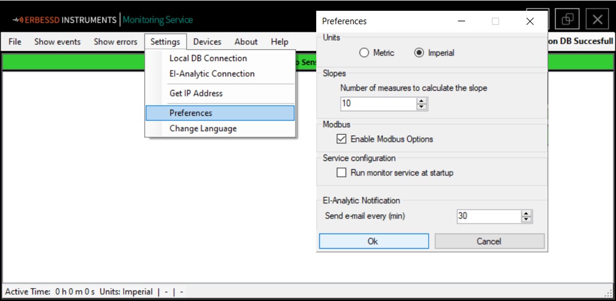
First, activate the Modbus options from the Preferences window on EI-Monitoring; after this you can find the Modbus Integration from the Settings tab on EI-Monitoring.
Gateway Configuration
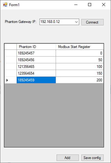
The first option we have is to register the gateway we want to transmit data to us. Select the option “Gateway Configuration” and the Gateway Configuration window is open. Here you will find a box with the legend Phantom Gateway IP. Type the IP shown in the Gateway display and click on Connect.
Once done you will see a list where you can fill with the Phantom ID of your sensors. Click Save Config to finish, after this, your sensors will begin to send raw data (in metric) to your OPC system. You can find an example of the data at the end of this document.
If you happen to reach the end of the list, just add a new row clicking the button Add.
Register
The Register option will let you get post processing data from the gateway including Envelope Acceleration and detailed RMS data. To configurate this option fist click on “Register” from the Modbus menu and the Modbus configuration window will open.
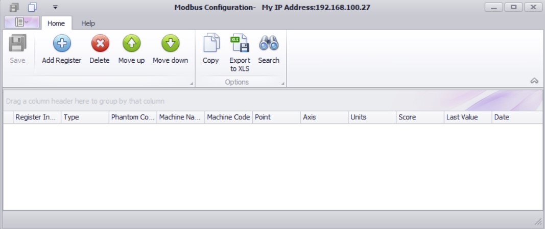
To obtain post processing data first click on “Add register” to open the database tree where you’ll find the machines you created on Digivibe along his analysis points and axes. By selecting one branch you’ll see all the parameters that are being collected from the sensors attached to the selected Axis/Point/Machine and by selecting the ckeckboxes the parameter list will be filled with the information, getting an identifier ID.
Example
The next holding register can be read by Modbus TCP client: