Top 10 Machine Faults - The Ultimate Guide on Vibration Analysis
What Are Machine Failures?
Machine failures occur when a machine or equipment stops functioning correctly, leading to partial or complete loss of its operational capabilities. These failures can result from various factors, including mechanical issues, electrical problems, software errors, or environmental conditions. Understanding the causes of machine failures is crucial for maintaining the efficiency, reliability, and longevity of industrial equipment.
Implementing a proactive maintenance strategy, such as predictive maintenance, can help identify potential issues before they lead to failures. Regular inspections, proper lubrication, and timely repairs are essential for keeping machines in good working condition. Additionally, training operators and maintaining a clean working environment can further reduce the risk of machine failures.
Lets explore the 10 most common machine failures and how to detect if you’re experiencing one of those.
Mechanical Machine Failures
Unbalance
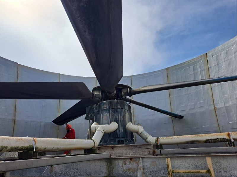
Unbalance occurs when a rotating machine, like a fan, motor, or any other rotating machine, has its weight unevenly distributed. Imagine a washing machine during the spin cycle with all the clothes bunched up on one side; it would shake a lot and make a lot of noise. This is similar to what happens when a machine is unbalanced.
When the weight inside a rotating machine is not evenly spread out, it causes the machine to wobble as it spins. This wobbling leads to several problems, including excessive vibration, which can be destructive. The machine will shake more than usual, and these vibrations can cause further issues. An unbalanced machine makes loud and noticeable noises, which can be annoying and indicate something is wrong. Additionally, constant vibration can cause parts of the machine to wear out faster or even break, leading to costly repairs and downtime.
Unbalance can be detected using accelerometers and specialized software like DigivibeMX M10. Thanks to these tools you’ll be able to review the Fast Fourier Transformation of the signal, which will show a very prominent peak at the machine’s rotation speed (1X). The severity of the unbalance depends on the type of rotating machine. To identify the expected values for different machines, you can refer to standards such as ISO 10816.
In some cases, you will need a balancing machine to perform the balancing job. A balancing machine helps by accurately identifying the unbalance and allowing for precise corrections. This equipment is essential for ensuring that the machine operates smoothly and efficiently, reducing wear and tear, and preventing potential damage.
Couple Misalignment
Couple misalignment occurs when the shafts of two connected machines, such as a motor and a pump, are not aligned correctly. This misalignment can happen in two main ways: angular misalignment, where the shafts are at an angle to each other, and parallel misalignment, where the shafts are not parallel and are offset horizontally or vertically.
Couple misalignment can lead to several problems in machinery, including increased vibration, excessive wear on bearings and couplings, and even mechanical failure if not corrected. This misalignment puts extra stress on machine components, causing them to wear out faster and potentially leading to costly repairs and downtime.
Misalignment can be detected using vibration analyzers to study the signal generated by the machines. The symptoms will differ depending on the kind of misalignment your machine is suffering. You can experience two kinds of misalignment: Angular Misalignment and Parallel Misalignment. Let’s see the differences:
Angular Misalignment: The shafts meet at an angle rather than being straight. Imagine two pencils touching at their tips but not lined up straight. The FFT will show a high peak at your rotor speed frequency (1X), followed by smaller peaks at 2 and 3 times your rotor speed (2X and 3X).
Parallel Misalignment: The shafts are parallel but offset from each other. Picture two pencils lying next to each other but not touching. The FFT will show a high peak at your rotor speed, followed by an even higher peak at 2X and a smaller peak at 3X.
Important: To detect misalignment, you will need data collectors that allow you to collect data from two points at the same time because the phase value is critical for this diagnosis.
Bent Shaft
A bent shaft is when the long, rotating part of a machine, like in a motor or pump, gets bent out of its original straight shape. This bending can happen for several reasons, such as putting too much force on the shaft, dropping it during handling, or issues from the manufacturing process.
When a shaft is bent, the machine often vibrates more than usual because the bent part doesn’t spin smoothly. This extra vibration can cause the machine to make unusual noises and wear out other parts faster. It might also cause misalignment, where connected parts like couplings and bearings don’t line up correctly, further increasing wear and inefficiency.
Detecting a bent shaft can be done through visual inspection, looking for any noticeable bends or deformations. Tools like vibration analyzers can pick up on the irregular vibrations caused by a bent shaft. Measuring tools, like dial indicators, can check if the shaft runs straight, and laser alignment tools can help ensure the shaft and connected parts are aligned correctly.
Resonance
Resonance is a phenomenon that occurs when the natural frequency of a system matches the frequency of an external force applied to the system. When a machine or its components resonate, the energy from the external force is efficiently transferred into the system, leading to excessive oscillations. These oscillations can amplify stresses on the machine parts, potentially leading to fatigue, damage, and failure.
To identify resonance in motors and other machinery, vibration analysis tools like hand held accelerometers in combination with powerful software like DigivibeMX or WiSER Vibe come in handy. One common method is to perform a frequency sweep, where the machine is gradually operated through a range of frequencies. By monitoring the vibration levels during this sweep, a peak in vibration amplitude will indicate the resonant frequency.
Want to know more about Resonance and Natural Frequency? Read this article.
Bearing Failure
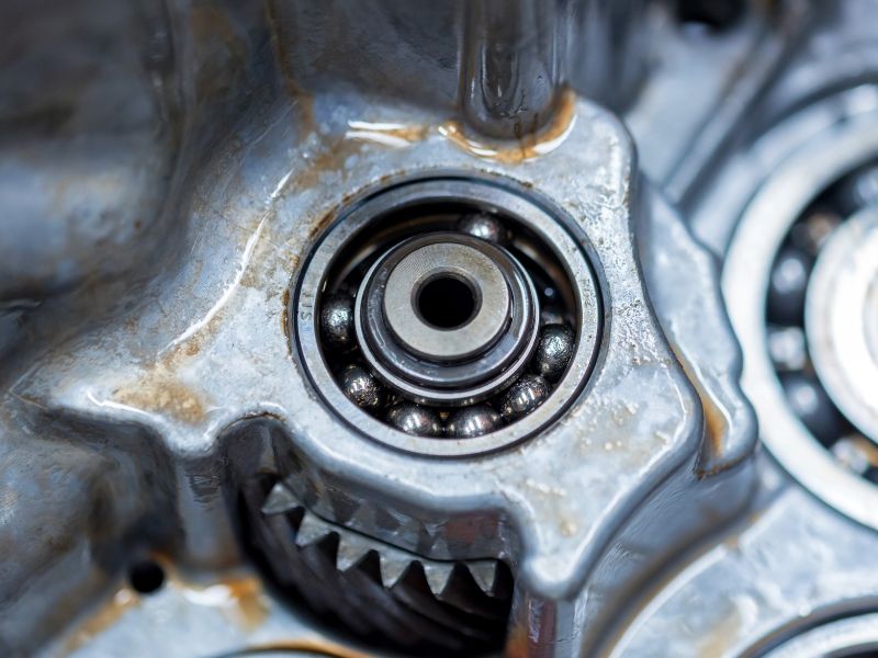
Bearing failure is one of the most common and critical machine failures. Bearings are essential components in rotating machinery, and their failure can lead to significant operational disruptions, costly repairs, and even catastrophic equipment damage.
Bearings are designed to support rotating shafts and reduce friction between moving parts. When bearings fail, they can no longer perform this function effectively, leading to increased friction, heat, and ultimately, machine breakdown. Common causes of bearing failure include:
- Contamination: Dirt, dust, and other contaminants can enter the bearing, causing abrasion and wear.
- Lubrication Issues: Inadequate, incorrect, or contaminated lubrication can lead to increased friction and heat.
- Overloading: Excessive loads can exceed the bearing’s design limits, causing deformation and damage.
- Misalignment: Improper alignment of the bearing and shaft can lead to uneven load distribution and premature wear.
- Fatigue: Over time, bearings can fail due to material fatigue from repeated stress cycles.
Understanding the characteristic fault frequencies of bearings is essential for diagnosing and addressing bearing issues effectively.
BPFO (Ball Pass Frequency Outer): Frequency at which a rolling element passes a defect on the outer race.
BPFI (Ball Pass Frequency Inner): Frequency at which a rolling element passes a defect on the inner race.
BSF (Ball Spin Frequency): Frequency at which a rolling element spins around its axis.
FTF (Fundamental Train Frequency): Frequency at which the bearing’s cage or retainer rotates.
There are vibration analysis software programs that include libraries of common bearings from various brands, aiding in the identification of these critical frequencies. Ensure the software you use has this feature, as it will significantly enhance the efficiency of your analysis.
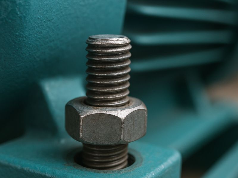
Mechanical Looseness
Mechanical looseness occurs when machine components are not properly secured or when there is excessive clearance in bearings, supports, or coupling areas. This condition can arise from improper installation, worn fasteners, or structural fatigue over time. Just like an unbalanced washing machine, a machine with looseness will produce higher vibration levels and can generate noticeable noise and erratic movement.
Looseness often leads to:
- Increased vibration, typically appearing in the FFT with strong amplitudes at the fundamental frequency and multiple harmonics (1X, 2X, 3X…).
- Premature wear of other components due to excess movement and impacting.
- Potential for sudden mechanical failures if left unaddressed.
To detect mechanical looseness, a vibration analyzer is key. By examining the spectrum, you’ll see elevated peaks not only at your running speed but also at multiples of that frequency. In some cases, you may need to perform phase analysis between different measurement points to confirm the movement or slippage in the machine’s structure. Use software like DigivibeMX M10 or WiSER Vibe to collect and compare data over time, which helps in pinpointing looseness before it becomes a major operational concern.

Gear Failure
Gear failure is a common and potentially expensive problem in systems that rely on gear-driven components, like gearboxes and speed reducers. Gears transfer torque and motion by meshing their teeth, but when these teeth become damaged, misaligned, or worn, overall machine performance can drop significantly. Symptoms of gear failure include unusual noises (such as whining or grinding), overheating, and increased vibration levels.
Common causes of gear failure include:
- Abrasive or erosive wear, often due to poor lubrication or contamination.
- Pitting or cracking on gear tooth surfaces caused by excessive load or fatigue.
- Improper backlash settings leading to repeated shock loads on the gear teeth.
In vibration analysis, gear failures typically show distinctive peaks at the gear mesh frequency (GMF) and its harmonics. You may also observe sidebands around those frequencies, which indicate modulation due to gear tooth damage or misalignment. Tools like DigivibeMX or WiSER Vibe can help identify these patterns; many of these platforms also have gear libraries that automate fault frequency detection. By regularly monitoring the gear mesh frequencies and their harmonics, you can prevent unexpected downtime and costly damage to your machines.
Non-Mechanical Failures
Electrical Failures
Electrical failures in rotating equipment are commonly linked to phase imbalances, winding shorts, loose connections, or degraded insulation. These problems often result in excessive heat, reduced torque, and, if left unaddressed, catastrophic motor damage.
One of the clearest signs of electrical problems is increased vibration at specific frequencies—typically harmonics of the line frequency (60 Hz or 50 Hz). For instance, a motor operating in North America that shows a strong vibration peak at 120 Hz (2X line frequency) in the FFT spectrum may be suffering from an electrical fault. Unlike mechanical issues, these patterns correlate directly with the power supply, not the rotational speed.
For more accurate detection, current sensors—such as those supported by systems like Defiant—can be used to compare real-time current consumption against typical motor behavior. Anomalies like unexpected current spikes, irregular harmonics, or unstable waveforms may point to winding faults, rotor bar defects, or phase imbalances. By correlating vibration data with electrical current signals in a unified monitoring platform, it becomes easier to identify the root cause of a fault and take early corrective action.
Electromagnetic Interference (EMI)
Electromagnetic interference (EMI) happens when external electrical signals disrupt monitoring or communication systems. This is especially common in industrial settings with variable frequency drives (VFDs), induction heaters, welders, or high-power equipment. While EMI doesn’t directly damage machinery, it can severely compromise data quality, leading to incorrect diagnoses or communication loss.
One common sign of EMI is erratic or intermittent vibration readings, particularly with wireless sensors. In the FFT spectrum, EMI may appear as high background noise or unusual peaks not aligned with running speed or harmonics. If spectral patterns seem inconsistent with the machine’s normal behavior, EMI should be considered a potential cause.
When monitoring current signals, EMI may manifest as waveform distortion or irregular harmonics, which can be detected using power quality analyzers or oscilloscopes. Comparing data across different time intervals, or turning off suspected EMI sources, can help confirm the interference. To mitigate EMI, it’s crucial to use properly shielded cables, EMI-resistant sensors, and grounding practices. Phase analysis and comparison of readings from multiple points can also help distinguish real mechanical issues from interference artifacts.
Thermal Overloading
Thermal overload occurs when equipment operates at elevated temperatures for extended periods, beyond its rated thermal capacity. This may be due to poor ventilation, excessive ambient heat, overloading, or internal inefficiencies such as poor lubrication or electrical resistance.
While temperature is typically monitored with thermocouples or RTDs, thermal stress can also influence vibration patterns. As components expand with heat, clearances change—especially in bearings—potentially causing friction, looseness, or misalignment symptoms in the vibration spectrum.
In systems like Phantom, temperature sensors can be integrated alongside vibration channels to detect thermal overload in real-time. Gradual increases in temperature correlated with rising vibration levels (especially in the axial or radial directions) often point to a heat-induced condition. Monitoring thermal trends over time is essential for avoiding unplanned shutdowns due to overheating.
Early Detection for Better Performance
Maintaining optimal machine performance requires a proactive approach to identifying and addressing the most common faults before they escalate. Through vibration analysis and complementary techniques, we can detect unbalance, misalignment, bent shafts, resonance, bearing damage, mechanical looseness, and gear failures in their early stages. Each of these issues, if left uncorrected, imposes stress on various components, leading to amplified wear, higher energy consumption, and eventual breakdowns. By employing appropriate diagnostic equipment and reliable software, such as DigivibeMX M10 or WiSER Vibe, facilities can monitor characteristic fault frequencies, track changes in key metrics, and plan timely interventions.
When these challenges are tackled promptly, the benefits extend beyond minimizing downtime. Proper machine health translates into improved safety for operators, reduced operational costs, and longer equipment lifespans. Moreover, well-maintained machinery underpins stable production cycles and consistent product quality. Systematic data collection, thorough inspections, and adherence to recommended maintenance practices are all critical steps in refining overall reliability. A strong focus on training and team collaboration ensures that anomalies are recognized early and corrective measures are taken swiftly. Ultimately, preventing or mitigating these seven pivotal failures allows facilities to enhance productivity and remain competitive in today’s demanding industrial environments. That is diligence in action.
Luis Sabido works as the Head of Customer Service and Technical Support at Erbessd Instruments. He is an experienced professional with 5 years of experience helping Erbessd Instruments’ customers worldwide master the health of their machines. Luis has studied Physics Engineering and is currently pursuing a second degree in Engineering in Technology and Information Systems.
ERBESSD INSTRUMENTS® is a leading manufacturer of Vibration Analysis Equipment, Dynamic Balancing Machines, and Condition Monitoring with facilities in Mexico, the USA, England, and India