Vibration analysis in a single touch. Learn how to use our new diagnosys tool; swiftly and accurately detects vibration anomalies, diagnosing potential machinery issues before they escalate.
1. What is the Auto-diagnosis Tool for?
This is an analysis tool offered by EI-Analytic. That functions as a breakdown of possible failures at the analyzed points, with an assigned percentage of probability of occurrence.
The percentages of probability of occurrence of such failures are based on a series of parameters called “Rules“. This tool can help you identify:
Static Imbalance
Couple Imbalance
Dynamic Imbalance
Parallel Misalignment
Angular Misalignment
Bent Shaft
Bearing Fault: Stage 2, 3, 4.
Cocked bearing
Bearing Looseness
For each failure, certain criteria or rules must be met to a greater or lesser extent. This tool offers the user to create his own rules with the failure conditions that he sets according to his needs.
2. What Do I Need?
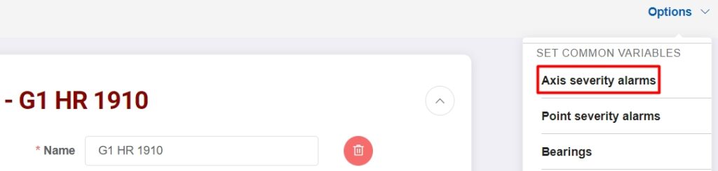
Severity alarms
By default, EI-Analytic includes ISO 10816 compliant severity alarms for Class 2 machines. While these alarms may be functional, they may not fit the specific needs of your machine.
Our recommendation is that you customize the severity alarm settings for each of your machines, especially if you plan to use the self-diagnostic tool.
Step 1.- Go to the EI Analytic platform and log in to your account with your email and password.
Step 2.- Enter the “Machine Manager” and choose the “Edit Machine” option. Here, find and select the machine you want to configure.
Step 3.- Choose the axis and points for which you want this new configuration to be applied.
Step 4.- Change the severity values with the “Edit” button for the velocity and acceleration envelope values. Once the new values are set, click on “Save”.
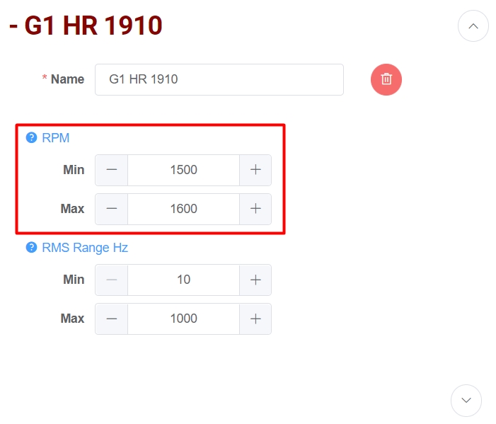
RPM range
Within the configuration of your machines, you will find the option to set the normal operating speed of your equipment. By default, these values are set to a range of 10 to 1000. If you wish to customize this configuration, follow these steps:
Step 1.- Go to the EI Analytic platform and log in to your account with your email and password.
Step 2.- Enter the “Machine Manager” and choose the “Edit Machine” option. Here, find and select the machine you want to configure.
Step 3.- Go to the point you want to configure and in the RPM section define the range that applies. Then save your configuration with the “Save” button.
Bearings
If you need to analyze a bearing for certain faults, such as checking its phase or a fundamental frequency, make sure you have previously added that bearing to your analysis point. To add bearings follow the steps below:
Step 1.- Go to the EI Analytic platform and log in to your account with your email and password.
Step 2.- Enter the “Machine Manager” and choose the “Edit Machine” option. Here, find and select the machine you want to configure.
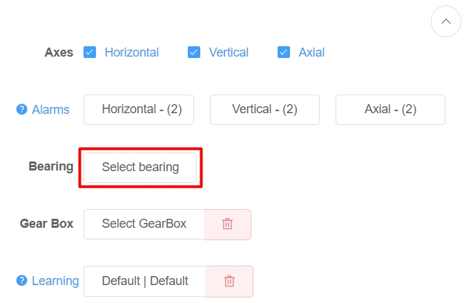
Step 3.- Go to the point you want to configure and in the “Bearing” section click on the “Select Bearing” button.
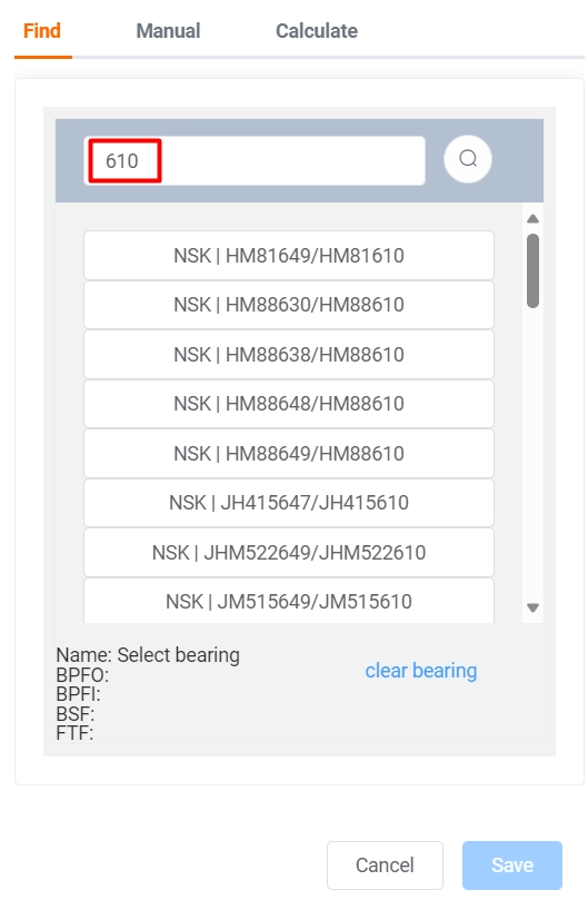
Step 4.- This will open a window where you can find your bearing from our library through the “Find” section. You can also use the “Manual” and “Calculate” sections to add a manual bearing.
Step 5.- Once you have selected/added the bearing. Click on “Save” and then also locate the “Save” button to save the configuration to the machine.
Couplings
In certain cases, it is necessary to analyze the coupling data of a machine. However, this will not be feasible unless we have created the coupling when initially configuring the machine.
Don’t forget that when using the machine manager, when creating or editing a machine, you have the option to add a coupling between the analysis points:
Step 1.- Go to the EI Analytic platform and login to your account with your email and password.
Step 2.- Enter the “Machine Manager” and choose the “Edit Machine” option. Here, find and select the machine you want to configure.
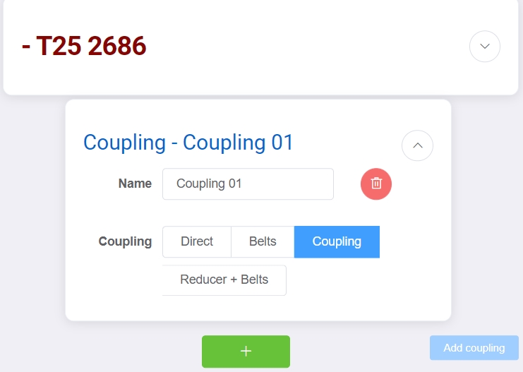
Step 3.- Go to your final point and select the “Add Coupling” button.
Step 4.- This will open a window where you can define the coupling characteristics.
Step 5.- Once the coupling is added you can add another point immediately or click “Save” to save the configuration inside the machine.
Synched measurements
On many occasions, it is necessary to record data on several axes or points at the same time. For example, if we need to compare phase between different axis, we must have data from at least two axis at the same time.
Fortunately, with triaxial sensors, recording in multiple axis is very simple. However, in situations such as coupled imbalance, it is necessary to record data at two different analysis points at the same time.
If you are using a WiSER device, you can incorporate an additional accelerometer to record data at both points simultaneously.
In the case of Phantom sensors, we have the “Phantom Sync” tool in Gateway 2.0, which allows you to receive data simultaneously from two or more sensors. This simplifies the task of collecting accurate and detailed information for your analysis:
Step 1.- Access the gateway configuration console.
Step 2.- Locate the “Phantom Sync” option.
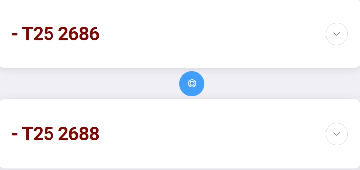
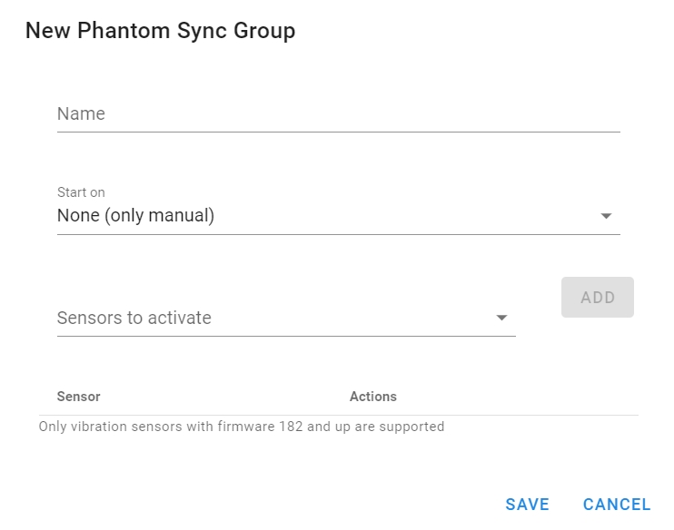
Step 3.- Click on “New” to open a window where you can add the sensors you want to have synchronized.
Step 4.- Click “Save” to save the activation group.
2. How to Access the Tool?
Step 1.- Enter the EI Analytic platform and log in with your email and password.
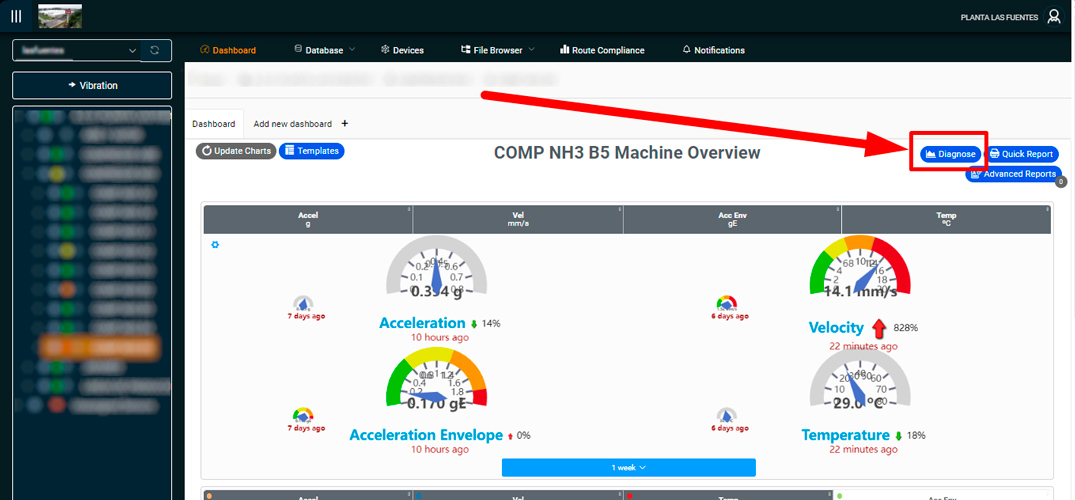
Step 2.- In the toolbar located at the top of the main screen, select and expand the “Database” section and choose the option named “Diagnose Manager”.
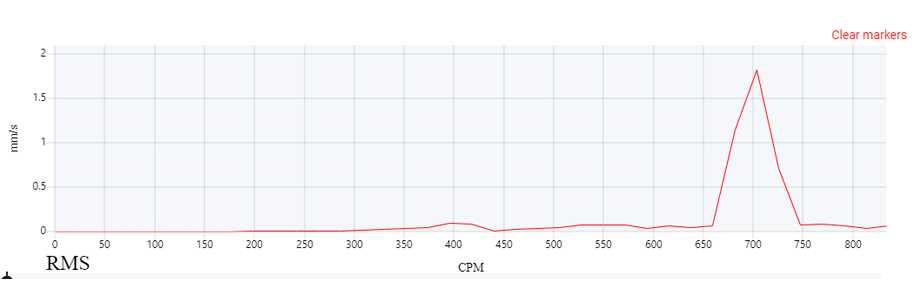
Step 3.- The system will direct you to the auto-diagnosis tool. In this section, you will see at first instance a graph in which the collected data will be represented and in the upper part the following options
Load Machine. Allows you to select the machine containing the data to be analyzed.
Diagnose Manager. Allows you to create your own conditional parameters by generating your own rules to identify a failure.
Another way to access the tool is through the machine tree, clicking directly on the machine followed by the point you want to analyze and going from there to the auto-diagnosis section.
3. How to Use the Tool?
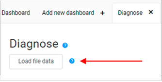
Step 1.- Load machine or point data by clicking on ‘Load file data’. You will be able to see in the dropdown menu the points to select (if you have more than one point). It is necessary to consider that the analysis in the tool is performed per point.
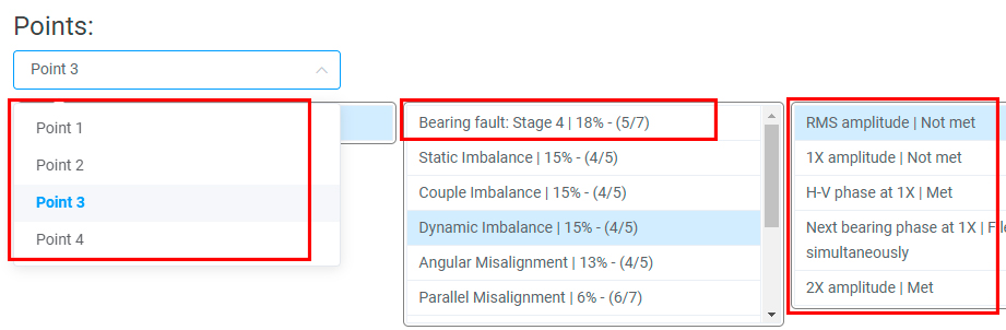
Step 2.- You will be able to see in the dropdown menu the points to select (if you have more than one point). It is necessary to consider that the analysis is performed per point.
A list of rules set by the system with probabilities of failure will appear in a drop-down menu, and the number of conditions that were met and those that were not met can also be displayed.
These rules are programmed by default. However, refer to the diagnostic builder section to add new rules.
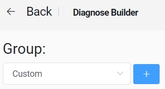
4. Diagnose Builder
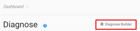
This manager assists you in creating new rules with specific conditions to detect the probability of failures occurring. To access the diagnose builder, simply click on the blue button located on the right side of the diagnose panel. Here, you can find the following sections:
Group: Use this section to arrange the various faults you add to the Diagnose tool.
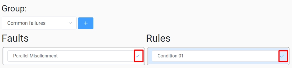
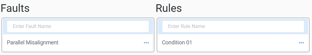
Faults and Rules: Name the fault and set the rule for the first condition to be met. To add it correctly you first need to click on the checkmark for the Fault and then click on the checkmark for the Rule.
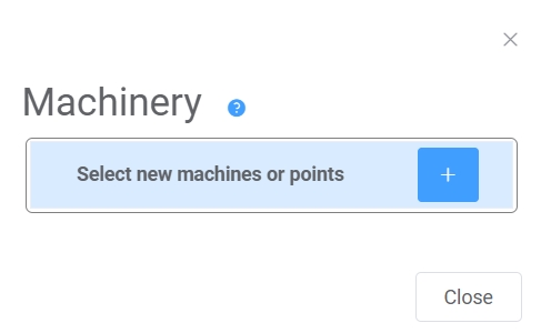
Add Machinery: The “Add Machinery” button to add machines or points to the currently selected fault. This will open a window that allows you to select the element you want to add within the database tree.
Name and ID: Name will be used for user reference and ID will be used internally to identify the rule.
Value A and B: The equation is composed of two values; both values are taken as reference to be compared and must be configured in the following fields:
Location: Set up as the point you are analysing, the complement to compare with or the coupling between them.
Axis: Select from which axis you are diagnosing.
Units: Choose the units of your preference.
Value type: Value of the signal that will be taken as a reference. You can choose options for FFT, TWF and Severity.
Range: Frequency range to analyze.
Order: Select the number of orders.
Bearings: You can select one or more bearing frequency faults. In case of multiple selections, the highest value will be used.
Operator: Select from various arithmetic operators to compare the parameters set in Value A and B.
Phase shift: Check the phase shift to compare the phase between Value A and B.
Factor: Give a ponder comparing the value A and B.