DRAGONVISION USER MANUAL
DragonVisionTM Tools
This section describes each of the elements of the DragonVision™ software. The menu-windows are show and the tools that make part of them, as well as its operation.
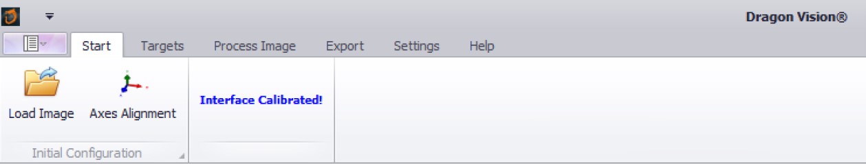
Start
In this part it shows the General view of the “Start” window of the Dragon Vision™ software:
Tools description:
Axes alignment: It allows you to draw the axes direction (H, V y A) in the previous loaded image.
Load image: It allows you to choose an image file from your computer.
By clicking this option, we can load an image file by locating it in the file browser shown to us. DragonVisionTM supports the following image fromats : .jpg, .jpeg, .bmp, .tif, and .dvf.
As you can see in the next image, DragonVisionTM shows an “interface calibrated!” because the device we’re using its pre-calibrated, in the case that the interface wasn’t calibrated its necessary to do it with the “calibrate device” tool, which we will talk about latter in the “Settings” section.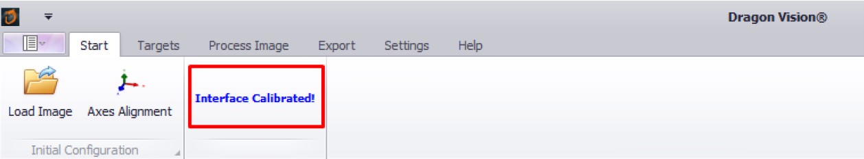
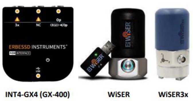
The following Erbessd Instruments interfaces and wireless devices are pre-calibrated on their chipsets. They do not require calibration in DragonVisionTM software:
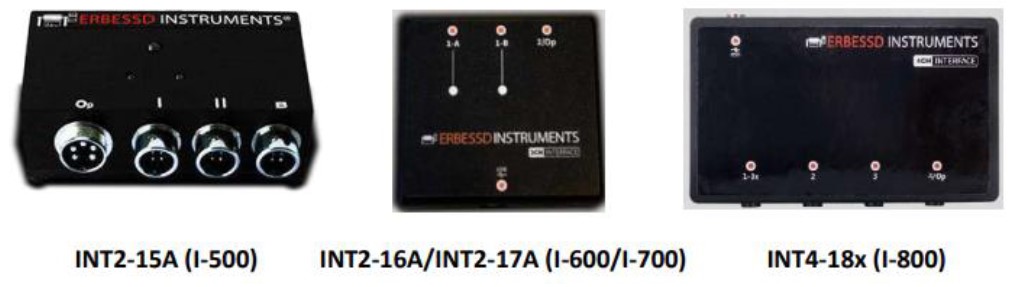
The following wired interfaces must be calibrated before performing the vibration data collection. It necessary to ensure the interface being use its correctly identified in the software before collect data, otherwise the collected data will be inaccurate. We will be talking about the calibration procedure later in this manual.
 —
—
Targets
The Targets section has a wide variety of options to work, in this window we can set the region that will be analyzed with a combination of different tools. Following we can see de target window general view and the description of all its tools.
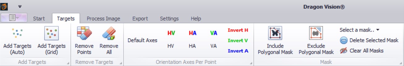
Tools description:
- Add Targets (Auto): It allows you to add targets by drawing a rectangular area with the mouse on the loaded image. The targets distribution its generated automatically by de software.
- Add Targets (Grid): Add analysis targets with the mouse by drawing a rectangular area. The targets are distributed in a uniform grid over the delimited area on the image.
- Remove Points: Eliminate the targets from the region selected by the mouse.
- Remove All: With this button you can eliminate all the previously created targets.
- Default axes: Acivating this button will establish the default DragonVisionTM axes colors for H, V and A.
Axes color: By using this tool, you can change the colors of the axes (H, V and A), there are three possible combinations:
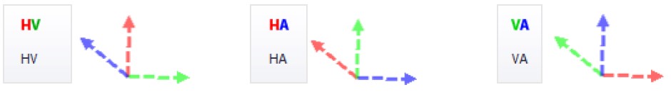
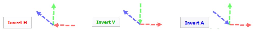
Orientation axes per point: With this option you can invert de direction of a previously draw axis. Various axes can be invert simultaneously. Example:
Include Polygonal Mask: It allows you to draw a polygonal mask (irregular polygon with unlimited sides number) with the mouse to choose the analysis region. With this tool the DragonVisionTM will only include in the analysis the area within the drawn polygon .
Exclude Polygonal Mask: It allows you to draw a polygonal mask (irregular polygon with unlimited sides number) with the mouse. With this tool the DragonVisionTM will NOT include in the analysis the area within the drawn polygon .
Select Mask: At last, in this section we can select and delete one of the previously generated masks, or well eliminate all the polygonal masks.
Process image
In the process image window, we can find the animation parameters and a preview tool, these features are especially useful to modify the animation according to our needs.
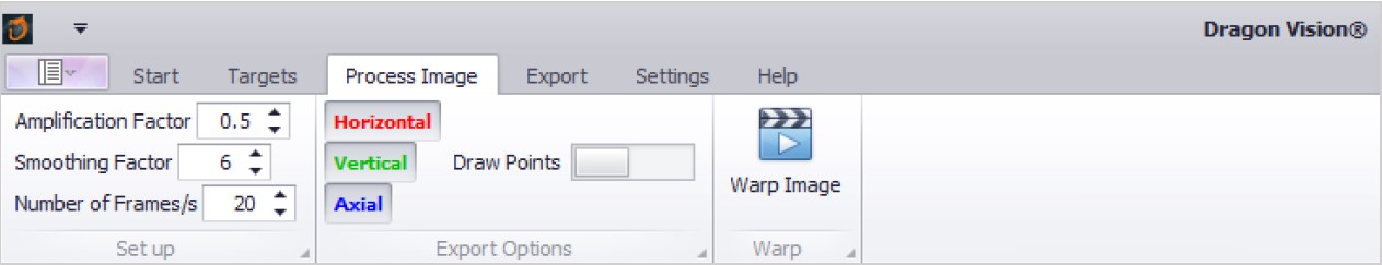
Explaining the operation of the tools:
Set up: In this section we can modify the amplification factor, the smoothing factor, and the number of frames in the video.
- Amplification factor: This factor amplifies the movement and displacement.
- Smoothing factor: Smoothens the transition between deformed and static regions.
- Number of frames: Number of created frames for the animation. Recommended is 20-30.
Note: You can find a more detail description of these parameters below in the “Warp configuration: Image processing” section of this manual.
Export options: This tool its used to activate or deactivate one or several axes in the final video and to show or hide the analysis targets previously drawn.
Draw points: If this option its active the final video will show the analysis targets.
Horizontal, Vertical, Axial (Global): If one of these boxes is unchecked, all movement along the selected global axis will not be shown.
Warp Image: It grants you the option to generate a preview of the warping animation, this its useful to edit the parameters in the way that is needed to satisfy the user requirements
Export
In the export window we find everything related to saving the video and the project. Following we can see the general view of this section and its tools.
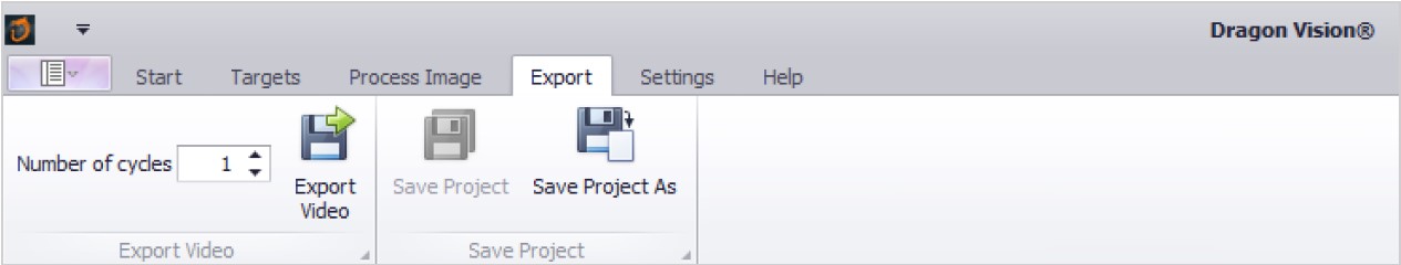
Export video: This option allows you to select the number of cycles (number of loops that will be repeated) that your video file will contain and choose a name for the file, the exporting formats supported by Dragon Vision are MP4 and AVI.
Save project: When you work with a preexisting project, you can save the changes instantaneously with this button.
Save Project As: By using this tool, you will be able to save a new project with a title of your choice. By clicking this button, the file browser is displayed, then we can find and select the location where we want to save the project.
Settings
In this section we have several important tools for creating a project.
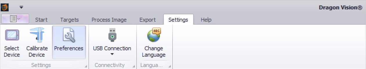
Following we describe the tools:
Select Device: It allows you to connect to a new device (interface or wiser.
USB Connection: We can change the type of connection with this option. The USB connection is used to measure data with wired devices such as the I500, I600, I700, I800, and Gx-400 interfaces.
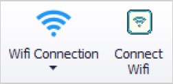
Wifi Connection: When switching to the Wi-Fi connection option, the “connect Wi-Fi” button is displayed, this one allows us to connect a wireless sensor (Wiser 3x).
Change Language: In this section we can change the language of the software. By pressing the “Change language” button, a window will appear where we can choose between English and Spanish language to work with.
Preferences
Preferences: With this tool we can modify the recording parameters and the sensitivity of the channels. When pressed, a window with two tabs, “Signal” and “Channels”, will be displayed.
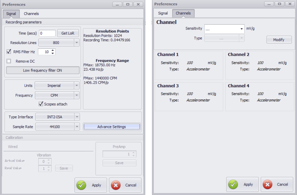
Following we describe the Signal Tab and its parts:
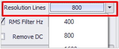
The box in the rigth set the recording data duration in seconds. The one in the left set the resolution lines of the signal.![]()
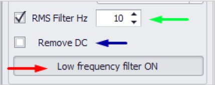
In the image to the rigth, the button pointed in green filter the frequencies with a lower RMS value that the one specified in the box, the one in blue removes the base noise and the red one deactivate both filters
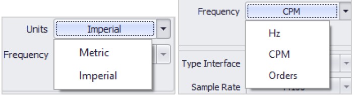
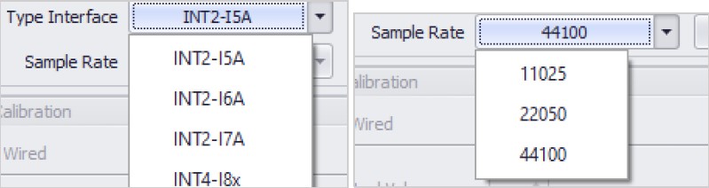
Below, the boxes in the left give us the option to change the units of the signal and frequency. In the one in the rigth we can choose the type of interface which we are connecting and the sample rate.
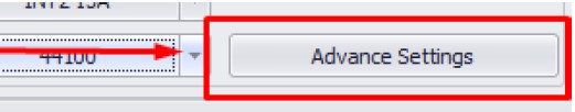
Warning: Advanced settings can cause irreparable damage to your computer and should not be changed. For more information feel free to contact the support team of Erbessd Instruments.
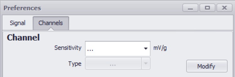
Now we describe the “Channels” tab: In this tab you can change the sensitivity of the channels. The number of channels will be configured automatically when choosing the interface type in the Signal tab.
Calibration
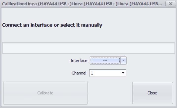
Calibrate Device: Allows us to calibrate a USB connected device.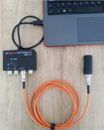
To calibrate, conect the 2 channel or 4 channel interface to the computer by an USB wire, then conect the calibration device in the “Op/Cal” port using a 5 pin tachometer wire as it show in the image.
DragonVisionTM should automatically detect the interface, if not, you will have to disconnect and connect again the device whit this window open. After that, select the channel where the calibration device is connected.
Once you select the interface and the channel, we press “Calibrate”. When the program finish loading, a message of “calibration succeeded” will appear, and with this the calibration its finish.
Help
In the Help window we can find information about DragonVisionTM and support tools for user.
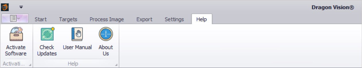
Tools description:
User Manual: It provides you with the DragonVision™ manual.
Check Updates: As its name say, Checks for possible updates.
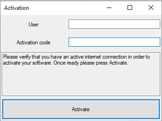
Activate software: With this tool you can activate the DragonVisionTM product by writing your license information.
A window is displayed with two empty boxes where you can enter your user and activation code provided to you in the buy of the DragonVisionTM product.
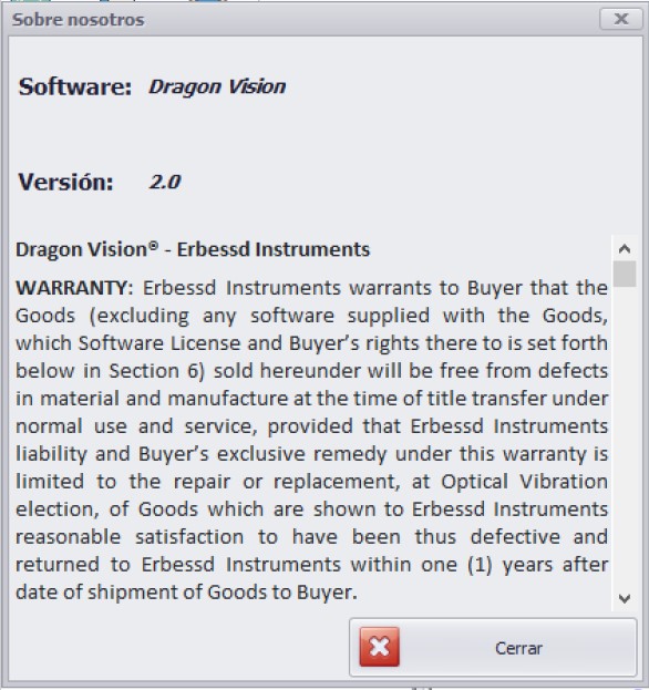
About Us: Pressing this button will bring up a window with information about the software and the warranty. The message is shown below:
Recording section
Under the tools of the windows menu, we have the section where the data is recorded.
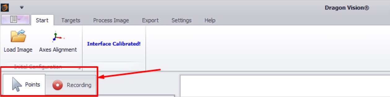
This section is described below:
Points: It let you choose the targets analysis group.
Recording: It shows the recording menu that allows you to record real data. The recording button shows the following tools:
- Record: Starts the data recording. Once the data is saved, the recorded values will be show in a table on the section below the recording button.
- Triaxial: Activating this button specifies that a triaxial sensor is being used.
- Sensor position: If you select a triaxial sensor, this tool will be available. Here we can select the position of the triaxial sensor to adjust the axes to the real position.
- Reference always: It allows us to select a reference accelerometer.
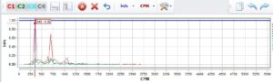
- Show FFT: Display the signal and spectrum generated by the recorded data.
- Pick a frequency: Once the signal and spectrum are show, this option allows us to pick a frequency on the FFT with the mouse. An arbitrary value can be choose (An example of this procedure its show later in the “Starting a project: Analysis area and data: Data recording”).
Starting a project
Image preparation
Load image
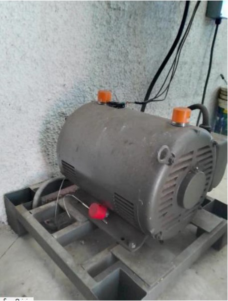
In the “start” window we click in load image to pick a file from our computer. Take at least one photo of the system that is being analyzed, where most of the measured points are shown.
We recommend an isometric view of the whole system to visualize the 3D components of acceleration. However, if more views are required, you can capture more images to produce animations of multiple views.
We recommend at least 2 Mpx image resolution (equivalent to Full HD resolution 1920 x 1080 px) for better looking animations.
Axes alignment
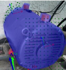
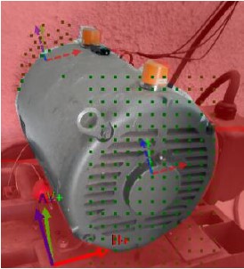
Using the “axes alignment” tool, click in the position where you want to set the origin of the global axis. We recommend setting the origin in the center of a shaft, bearing, or NDE of a motor to have the machine axis and orientation as reference.
Draw first the H+ (red), then V+ (green) and finally A+ (blue) axis according to most of your accelerometer measurements orientation, an auxiliary line will follow your pointer to visualize the axis orientation, you can extend the line arbitrarily to ensure alignment, click when you have the desired orientation to set that specific axis. Left click to start, right click to finish.
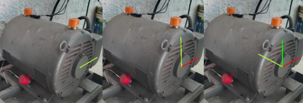
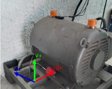
Once all the axes are set, a global coordinate system will show in the left lower corner of the image.
Analysis area and data
Generating analysis targets
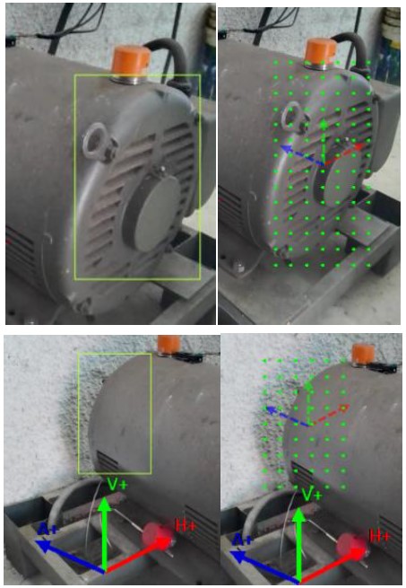
Select the measurement area of the image by drawing it with the mouse to generate the deformation points. You can automatically generate the targets or use the grid option.
Polygonal mask
You can add a polygonal mask to select the analysis area and exclude the rest of the image. We could use either of the “include” or “exclude” options, or a combination of both masks for a more complex analysis.
By default, if no masks are created, Dragon Vision will only warp the region enclosed in the convex envelop formed by all the points (auto and grid).
Option 1: Include mask:
Option 2: Exclude mask:
Data recording
In the settings window, we select USB or WIFI connection according to the device that is been used. Select the targets and begin recording. The animation will have the respective spectrum data for the previously generated targets.
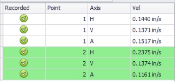
Once we collect the data, choose the frequency in the spectrum that we’re going to use for the animation, use the mouse to arbitrary select the value and press the left click to confirm selection. Follow this action for every target group. Its important to select the sensor position in the software.
Warp configuration
Image processing
The warping parameter are modifying in the process image window to obtain the desire animation. These parameters can be readjusted freely to preview the warped video. Consider the following:
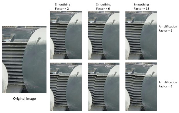
- Amplification factor: Value greater than 0, this factor amplifies displacement and motion. When this value is large, it is recommended to reduce the “Smoothing Factor” to avoid affecting neighboring static regions.
- Smoothing factor: Value >= 1, this factor that smoothens the transition between deformed and static regions. Larger values will affect greater areas out of the warped zone. For large amplification, it is recommended to reduce this value to avoid affecting neighboring regions. Smoothing factor=1 creates a sharp transition of displacement.
Example:
- Number of frames: Number of created frames for the animation. Recommended is 20-30. If more temporal details are required, this value can be increased for a smooth animation in time. Increasing this value will decrease the animation speed and viceversa.
- Draw points: If this check box is marked, the animation will show the created points marked in green in the video for reference of the user.
- Horizontal, Vertical, Axial (global): If this box is unchecked, all movement along the selected global axis will not be shown. This is useful in case we want to visualize separately the components of the displacement; we can show any combination of single (e.g., only axial movement), two (e.g., movement in a plane) or all axes (3D movement).
Parameters preview
Once all the parameters are set, click on “Warp Image”, to create a preview animation of the deformation. To close this window, press any key or click anywhere in the preview window. You can then fine tune any parameters and iterate to adjust the animation to your specific needs. Once the result is achieved you can proceed to save this video
Saving the video
Once you are satisfied with the previewed results, select the number of cycles (number of loops that will be repeated) that your video file will contain and choose a name for the file, the exporting formats supported by Dragon Vision are MP4 and AVI. Only one loop is required to reproduce the whole cycle of the animation and endless playback can be enabled in your preferred media player (we recommend VLC) or power point player. However, if required you can increase the number of cycles.
Note: A large value for this parameter may produce larger files.