The spec sheet gives you a bandwidth. The mount decides how much of it you get.
Every wireless vibration sensor on the market advertises a frequency range. Fewer of them tell you that the number was measured on a calibration shaker, with the sensor bolted to a block of steel through a stud — and that on your machine, with the base they ship and the mount you use, the usable range can be a fraction of it.
The reason is not electronics. It is mechanics, and it is old: the sensor and its mount form a spring-mass system with its own resonance, and above a fraction of that resonance the reading is no longer the machine’s vibration but the sensor’s. Where that resonance falls depends on three things you can see by looking at the sensor: how heavy it is, how stiff its joint to the machine is, and how high its mass sits above that joint.
This article explains those three things, what they imply for the way a sensor should be built, and how we built the PHANTOM® Gen 4 around them. The physics is in ISO 5348, the standard on the mechanical mounting of accelerometers, and in any vibration textbook; none of it is ours.
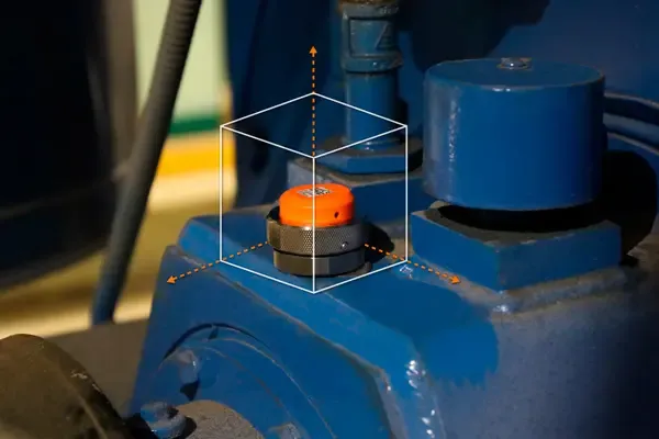
The sensor is part of the measuring chain
Bolt a mass to a surface and you have built an oscillator. The mass is the sensor; the spring is everything between the sensing element and the machine — the housing, the base, the thread or the glue, the surface finish. That system has a natural frequency, the mounted resonance, and it follows the oldest formula in vibration:
fn = (1 / 2π) · √(k / m)
where k is the stiffness of the joint and m the mass sitting on it. Stiffer joint, higher resonance; heavier sensor, lower resonance. Near that frequency the sensor amplifies what it sees; well below it, the sensor follows the surface faithfully. That is why ISO 5348 and the accelerometer manufacturers give the same rule of thumb: keep the measurement below roughly a fifth of the mounted resonance if you want the amplitude error to stay small. A sensor whose mounted resonance sits at 10 kHz is a 2 kHz sensor in practice — whatever the electronics can sample.
So the question to ask about any wireless sensor is not “what bandwidth does the chip have” but “where is the mounted resonance, with the base you ship and the mount I will use”. The three variables that answer it are all visible from the outside.
Three things set the mounted resonance
Mass. More mass on the same joint means a lower resonance — it is the m under the square root. Mass by itself is not a fault: a sensor needs a housing that survives a plant, and the stiffness of that housing is part of the joint. What matters is where the mass is, which brings us to the third variable.
Stiffness of the joint. This is the variable with the widest swing, because the joint is chosen at installation, not at the factory. ISO 5348 lists the options from best to worst coupling: a threaded stud into the machine, a thin layer of adhesive, and a magnet. The ranking is not in dispute. A stud loads the sensor against a machined surface with the full stiffness of the thread; adhesive is a compliant layer whose stiffness depends on its thickness and cure; a magnet is a second mass on a second, softer joint. Each step down the list lowers the mounted resonance, and with it the usable band.
Height of the centre of mass. A spring-mass system also has a rocking mode. Picture the sensor as an inverted pendulum standing on its joint: the higher its centre of mass sits above the mounting plane, the larger its moment of inertia about that plane, and the lower the frequency at which it rocks. Rocking is worse than axial resonance, because it converts the machine’s motion into a spurious transverse signal on the other axes — the sensor reports vibration that is its own. A tall, narrow body on a small base rocks at a low frequency; a low, wide body on a large base barely rocks at all.
Both drawn to the same scale. The glued disc under the tall sensor is, on its own, taller than the height at which the Gen 4 carries its whole centre of mass.
The three variables multiply. A heavy sensor on a stiff stud can outperform a light one on glue; a light sensor with its mass concentrated high on a compliant base can lose most of its advertised band. Two sensors of the same weight are not the same sensor.
The three ways to mount a sensor
| Mount | The joint | What it does to the usable band | When it is the right choice |
|---|---|---|---|
| Threaded stud | Thread into the housing, sensor torqued down | The reference. The mounted resonance is set by the sensor itself | Permanent monitoring, high-frequency faults, bearings |
| Adhesive | A layer of epoxy or a glued pad | Lower resonance, and it drifts with cure, thickness and heat | Surfaces that cannot be drilled, if the band you need is low |
| Magnet | A magnet, then the sensor on top of it | Lowest resonance: a second mass on a softer joint | Route collection and one-off checks |
The stud is what the accelerometer manufacturers calibrate against, and it is what ISO 5348 recommends for anything permanent. The other two are compromises the analyst accepts knowingly for a route or a machine that cannot be drilled — not defaults a vendor should ship for permanent monitoring without saying what they cost in bandwidth.
Mass loading: when the sensor changes the machine
The joint works in both directions. A sensor bolted to a structure adds its mass to that structure, and if the structure is light, the sensor shifts the very resonances it is supposed to measure. The usual rule of thumb is that the sensor should weigh a small fraction of the dynamic mass of the surface it sits on — a tenth is the number most often quoted. On a bearing housing of tens of kilograms, 187 g is nothing. On a thin sheet-metal guard or the free end of a small motor, the same 187 g is not, and no sensor of that class should be mounted there without knowing it.
This is the other reason the mass of a sensor should be spent where it does work — on the stiffness of the housing and the joint — and not on carrying a large cell or a long radio high above the machine.
How the PHANTOM® Gen 4 is built, and why
Take the three variables and design backwards from them, and you arrive at a shape: a low, wide puck threaded to the machine, with its mass at the bottom. That is the Gen 4: 46 mm across, 34.5 mm tall, 187 g, on a 1/4-28 UNF thread. The numbers below are off the CAD model, published here because an article that asks other vendors for their figures has no business withholding its own.
- The centre of mass sits 10.25 mm above the mounting plane — under a third of the sensor’s 34.5 mm height. That is the number the rocking mode answers to, and it is low because of where the steel is, not because the sensor is light.
- 83 % of the mass is steel, and the heavy part is the part touching the machine. Of the 187 g, 110 g are the 304 stainless-steel base that carries the thread, 44.5 g the steel ring that closes the housing, and 32 g the plastic cap with the electronics under it.
- The joint is a thread cut into that base. 1/4-28 UNF-2B, 5 mm deep, straight into the 304 stainless steel and torqued to 3.0 ± 0.3 N·m — the mount ISO 5348 puts first. No adapter, no pad and no glue line between the sensor and the machine: the stiffness of the joint is the stiffness of the housing it is threaded into. Where a surface cannot be drilled we do ship a stainless adhesive base, and by the argument above it costs on both counts: 20 g more mass, carried higher, on a glue line instead of a thread.
- The top is plastic because a radio cannot see through steel. The ABS cap holds the antenna where a metal can would shield it. Steel where the vibration enters, plastic where the signal leaves — the two materials are where the physics wants them.
- The sensing element sits 23.48 mm above the mounting plane, potted in epoxy. The MEMS is on a board inside the cap, and the board, the antenna and the element are embedded in epoxy resin, so the assembly is a solid block rather than a card standing on connectors — there is no loose circuit board with a resonance of its own between the machine and the element. Every wireless MEMS sensor has this distance; few publish it.
- It is small because it carries only what the point needs. Triaxial vibration and temperature. Everything else in the PHANTOM® family — current, RPM, thermocouples, the thermal camera, the 4–20 mA and 0–10 V inputs — is a separate module, so no bearing has to carry a housing sized for variables it does not use.
Two shapes, side by side
The all-in-one sensor is the other answer to the same problem, and it is worth comparing without adjectives, on published dimensions. Several makers build it, and the shape is consistent between them: a taller body carrying ultrasound, a magnetometer, a larger radio and a larger cell, standing on a separate base that is glued or screwed to the machine.
Low puck on a stud
PHANTOM® Gen 4: 46 mm across, 34.5 mm tall, 187 g, threaded 1/4-28 UNF straight into the machine. 83 % of that mass is steel and most of it is the base, which puts the centre of mass 10.25 mm above the mounting plane — measured on the CAD model, not estimated. Height-to-footprint ratio: about 0.75.
Tall body on a glued base
A representative example, from a published datasheet in this class: a body of 40 × 71 × 40 mm and 180 g, on a base of 22 or 50 g that has to be glued or screwed to the asset. The drawing shows what that base is: a 20 mm disc with an M6 thread the sensor screws onto. The body — ultrasound, magnetometer, radio and battery inside — stands on a joint less than half the width of the Gen 4’s, through a 6 mm thread. Height-to-footprint ratio at the joint: about 5.
Same mass, to within seven grams. One puts it low, on a 46 mm base and a thread cut into steel; the other puts it high, on a 20 mm glued disc and an M6 thread.
There is one comparison that needs no assumptions about what is inside either sensor. The Gen 4’s entire centre of mass, at 10.25 mm, sits below the height at which the other sensor’s body begins — the glued disc under it is 20 mm tall on its own. Wherever that body carries its mass internally, all of it is above a line the Gen 4’s centre of mass is already under.
Everything in the sections above says those two shapes do not have the same mounted resonance, and therefore not the same usable band — whatever their spec sheets say about sampling. We are not going to put a number on someone else’s sensor: the honest way to settle it is the curve, and the honest question is the one below.
This article is about shape, not about brands, and the proportions above describe a class of sensor rather than one product. If you want the comparison by name — which systems, what each costs to run over five years, and where each one wins — we do that in The 4 Best Vibration Monitoring Systems in 2026, our own weak spots included.
What to ask before you trust a spec sheet
- Show me the frequency-response curve of the sensor as mounted, with the base you ship — not the bare element on a calibration block.
- Where is the mounted resonance, and what is the usable band at a fifth of it?
- How is it attached: stud, adhesive or magnet? If adhesive, what happens to the resonance at 80 °C?
- How tall is the body, how wide is the joint it stands on, and where is its centre of mass?
A vendor who has measured its sensor will answer in a minute. One who has not will change the subject to the sampling rate.
We have that curve for the PHANTOM® Gen 4: stud-mounted, measured on a certified shaker. It is available to our customers on request, and it is the first thing we hand over when someone asks question 1 above.
FAQs about vibration sensor mounting and shape
What is the mounted resonance of an accelerometer?
The natural frequency of the sensor on its mount, treated as a mass on a spring: the sensor’s mass on the stiffness of the joint between it and the machine. Near that frequency the sensor amplifies the vibration instead of following it, so the usable measuring band ends well below it. ISO 5348 and the accelerometer manufacturers place that limit at roughly a fifth of the mounted resonance for small amplitude error.
Does a heavier vibration sensor measure worse?
Not by itself. Mass lowers the mounted resonance, but where the mass is matters more than how much there is: a heavy sensor with its mass low and a stiff threaded joint keeps a high resonance, while a lighter sensor with its mass high on a glued base can lose most of its band to a rocking mode. Mass also loads light structures, so a sensor should weigh a small fraction of the surface it sits on.
Is stud mounting really better than adhesive or magnetic mounting?
Yes, and it is not close. ISO 5348 ranks the mounts by coupling stiffness: threaded stud first, adhesive second, magnet last. Each step down lowers the mounted resonance and narrows the usable band. Adhesive and magnets are legitimate for routes and for surfaces that cannot be drilled; for permanent monitoring, the stud is the reference.
Why is the PHANTOM® Gen 4 a low, wide puck?
Because a low, wide body on a thread keeps the centre of mass close to the joint and the joint as stiff as the machine, which keeps the mounted resonance and the rocking mode above the band that matters. Of its 187 g, 154.5 g are stainless steel and most of that is the base, which puts the centre of mass 10.25 mm above the mounting plane — under a third of its 34.5 mm height. The plastic cap on top is only where the antenna needs to see out. It is small because it carries triaxial vibration and temperature and nothing else; the other variables are separate PHANTOM® modules.
Further reading